T
Tom Griffin
Forum Guest
Register Today
I thought would share my technique used to engrave personalized grip medallions on a recent project, a 1911 Officer's Model.
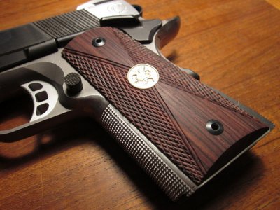
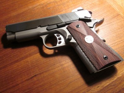
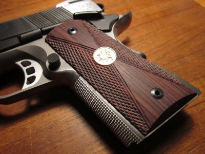
I liked the look of dark colored grips with a metal medallions inlaid into them such as those from STI and Packmayr, so I decided to make a pair using my family crest (Griffin) as the medallion. I chose Kingwood to make the grips because of its density and hardness, as well as its oil content. Using grips from another 1911 as patterns and compensating for the smaller size of the Officer's Model, I roughed them out on the band saw, drilled and counter-bored the mounting holes and screwed them to a piece of wood for use as a handle. Then I finish shaped them on the belt sander and added all of the various clearance cuts for the ambidextrous safety, the spring plunger and the magazine release mechanism.
I had already checkered the front strap of the frame, but doing it on wood would be a new experience. I picked up a few basic checkering tools from Midway, decided on a pattern and got to work. It was pretty uneventful but the pattern did get away from me once and I had to sand it down a bit to get it straightened out. Thankfully the grips were on the thick side so there was room. I found it challenging to keep the lines straight as they progressed across the field. Occasionally switching to the single cutter helped adjust them along the way. The kingwood checkered beautifully, even better than the scrap piece of walnut I was practicing on. The most difficult part was to keep the lines from cutting into the X shaped bead across the middle. The best way to avoid that was to finish all the checkering before adding one more row to use for the bead.
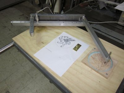
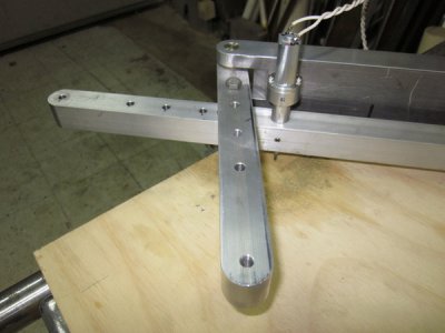
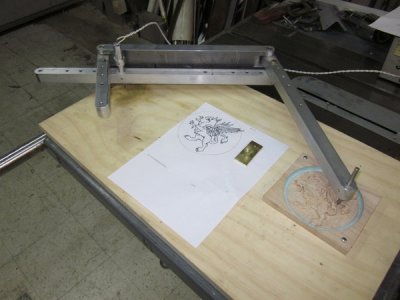
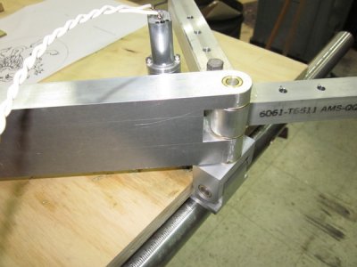
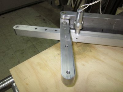
Once the checkering was finished, it was time to tackle the medallions. Since I couldn't see myself hand engraving a Griffin into a 1/2" diameter medallion, building a pantograph was a necessity. The internet provided numerous plans and ideas that enabled me to come up with a suitable design. I built a CAD model of it first to check the operation before cutting any metal. I used aluminum for the arms with close fitting flanged brass bushings and hardened and ground stainless round for the pivots. The spindle was made with some class 5 flanged bearings I had laying around with a small DC motor for power. I was using a tiny, pointed carbide burr to do the cutting so it didn't take much of a motor to drive it. I used a set screw to hold the tool but now that I know it works, I'll probably redesign the spindle to use collets and maybe an offset belt drive motor to allow for larger cutters.
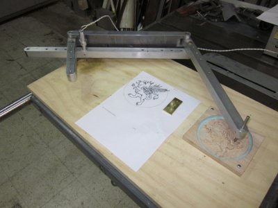
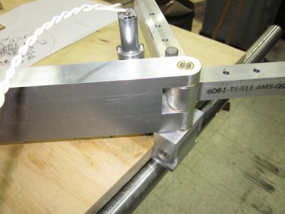
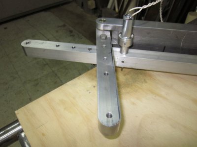
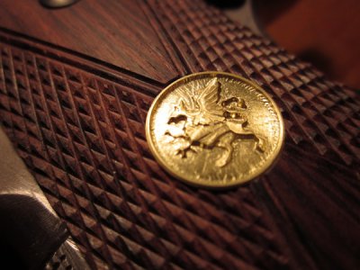
Once the pantograph was built, a pattern for the Griffin was next in line. I scoured the internet once again and came up with a nice simple drawing of a good looking Griffin and used that as a pattern to carve out a 3D version out in hard maple. A 10:1 ratio was the plan, so the pattern ended up at five inches in diameter. The pantograph will also do 1:2, 1:3, 1:4 and 1:6 reductions. After doing a trial run, I decided to add a fillet around the rim which is what the green stuff is in the pictures. One part of the pantograph that is not shown in the pictures is the counter balance. When I first tried to use it, it was obvious that some sort of arm would be required to take the weight off the stylus. I just cobbled something together to do cut the medallions but plan on making a permanent counterbalance later on.
With an appropriate high speed spindle, the pantograph could be used to engrave wood directly. Not sure if it would work for checkering, but it would certainly work for monograms or scroll work, although the patterns would need to be at least two or three times scale. I used 10:1 for the brass. Otherwise, the tool would tend to dig in and be hard to control.
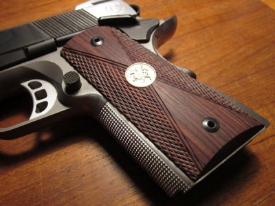
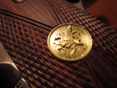
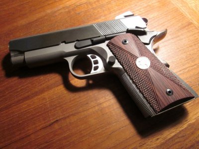
The medallions are brass and will be nickel plated to match the slide on the pistol. The rest of the frame will be blued. The medallions are pretty much as machined. If you follow the link below, you can get to monster sized images that show every machine mark. I touched them with some Scotch Bright while they were in the lathe, but I didn't want to do too much and risk losing detail.
More and larger pictures are available HERE.
Due to a number of requests, I have created the following PDF files which include detail drawings and an assembly drawing for the pantograph.
Pantograph Assembly
Rear Arm
Bushings
Long Side Arm
Mounting Bracket
Pivot Yoke
Short Side Arm
Spindle Arm
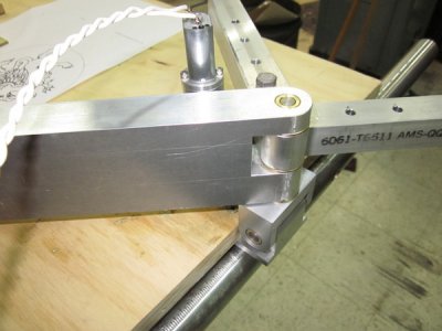
I used close tolerance AN bolts for the pivot points that set the ratio, with nylon lock nuts and washers. If you use hardware store variety bolts, be sure to mic them and ream the holes to suit, the less play in the pivots the better because it all adds up. The pins in the Pivot Yoke and the Rear Arm are made form 1/4" ground shafting that I had on hand. McMaster Carr sells it. One improvement I would consider after using the pantograph would be to modify the mounting bracket to include adjusting slots to set the center of the horizontal pivot to the height of the work. No details of the spindle were included because I just used parts on hand to make it. It was made from small flanged ball bearings and a DC motor and uses 1/8 burrs or cutters. You could devise your own or adapt a Dremel. The stylus should be the same shape as the cutting tool you are using but proportionally larger. The aluminum construction worked fine for cutting brass but would likely be too springy to cut steel. Making the arms out of steel bar might be a better option. A counter balance of some sort needs to be added. When I was cutting the medallions for my grips I just clamped a piece of angle on the rear arm and added weight until it balanced.
Have fun!
Tom
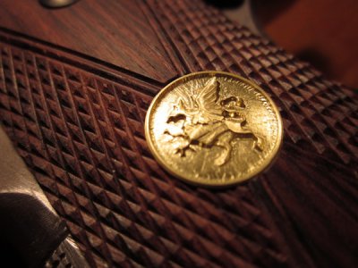
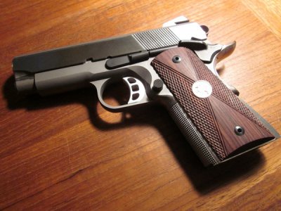
I liked the look of dark colored grips with a metal medallions inlaid into them such as those from STI and Packmayr, so I decided to make a pair using my family crest (Griffin) as the medallion. I chose Kingwood to make the grips because of its density and hardness, as well as its oil content. Using grips from another 1911 as patterns and compensating for the smaller size of the Officer's Model, I roughed them out on the band saw, drilled and counter-bored the mounting holes and screwed them to a piece of wood for use as a handle. Then I finish shaped them on the belt sander and added all of the various clearance cuts for the ambidextrous safety, the spring plunger and the magazine release mechanism.
I had already checkered the front strap of the frame, but doing it on wood would be a new experience. I picked up a few basic checkering tools from Midway, decided on a pattern and got to work. It was pretty uneventful but the pattern did get away from me once and I had to sand it down a bit to get it straightened out. Thankfully the grips were on the thick side so there was room. I found it challenging to keep the lines straight as they progressed across the field. Occasionally switching to the single cutter helped adjust them along the way. The kingwood checkered beautifully, even better than the scrap piece of walnut I was practicing on. The most difficult part was to keep the lines from cutting into the X shaped bead across the middle. The best way to avoid that was to finish all the checkering before adding one more row to use for the bead.
Once the checkering was finished, it was time to tackle the medallions. Since I couldn't see myself hand engraving a Griffin into a 1/2" diameter medallion, building a pantograph was a necessity. The internet provided numerous plans and ideas that enabled me to come up with a suitable design. I built a CAD model of it first to check the operation before cutting any metal. I used aluminum for the arms with close fitting flanged brass bushings and hardened and ground stainless round for the pivots. The spindle was made with some class 5 flanged bearings I had laying around with a small DC motor for power. I was using a tiny, pointed carbide burr to do the cutting so it didn't take much of a motor to drive it. I used a set screw to hold the tool but now that I know it works, I'll probably redesign the spindle to use collets and maybe an offset belt drive motor to allow for larger cutters.


Once the pantograph was built, a pattern for the Griffin was next in line. I scoured the internet once again and came up with a nice simple drawing of a good looking Griffin and used that as a pattern to carve out a 3D version out in hard maple. A 10:1 ratio was the plan, so the pattern ended up at five inches in diameter. The pantograph will also do 1:2, 1:3, 1:4 and 1:6 reductions. After doing a trial run, I decided to add a fillet around the rim which is what the green stuff is in the pictures. One part of the pantograph that is not shown in the pictures is the counter balance. When I first tried to use it, it was obvious that some sort of arm would be required to take the weight off the stylus. I just cobbled something together to do cut the medallions but plan on making a permanent counterbalance later on.
With an appropriate high speed spindle, the pantograph could be used to engrave wood directly. Not sure if it would work for checkering, but it would certainly work for monograms or scroll work, although the patterns would need to be at least two or three times scale. I used 10:1 for the brass. Otherwise, the tool would tend to dig in and be hard to control.


The medallions are brass and will be nickel plated to match the slide on the pistol. The rest of the frame will be blued. The medallions are pretty much as machined. If you follow the link below, you can get to monster sized images that show every machine mark. I touched them with some Scotch Bright while they were in the lathe, but I didn't want to do too much and risk losing detail.
More and larger pictures are available HERE.
Due to a number of requests, I have created the following PDF files which include detail drawings and an assembly drawing for the pantograph.
Pantograph Assembly
Rear Arm
Bushings
Long Side Arm
Mounting Bracket
Pivot Yoke
Short Side Arm
Spindle Arm
I used close tolerance AN bolts for the pivot points that set the ratio, with nylon lock nuts and washers. If you use hardware store variety bolts, be sure to mic them and ream the holes to suit, the less play in the pivots the better because it all adds up. The pins in the Pivot Yoke and the Rear Arm are made form 1/4" ground shafting that I had on hand. McMaster Carr sells it. One improvement I would consider after using the pantograph would be to modify the mounting bracket to include adjusting slots to set the center of the horizontal pivot to the height of the work. No details of the spindle were included because I just used parts on hand to make it. It was made from small flanged ball bearings and a DC motor and uses 1/8 burrs or cutters. You could devise your own or adapt a Dremel. The stylus should be the same shape as the cutting tool you are using but proportionally larger. The aluminum construction worked fine for cutting brass but would likely be too springy to cut steel. Making the arms out of steel bar might be a better option. A counter balance of some sort needs to be added. When I was cutting the medallions for my grips I just clamped a piece of angle on the rear arm and added weight until it balanced.
Have fun!
Tom


Last edited by a moderator:


