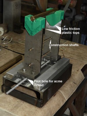
As I understand it, the function of the dovetail ways is to keep the V-blocks aligned while allowing the distance between V-blocks to be changed.
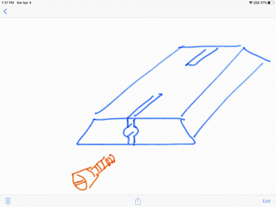
I'm thinking there is an easier way. Instead of using dovetails, think "box-ways". The bases of the V-blocks could straddle a rectangular base or they could guide in a slot in the base. Either of the box-way options only need one flat vertical plane and one flat horizontal plane (not equally spaced angled planes) on each part. Clamp the linear motion with lock screws behind a gib, bearing opposite the vertical guide plane.
I hope that's clear enough. If it makes no sense, let me know and I can generate a rough sketch.
Depending on the precision you're trying to achieve, I'm hoping you have access to heat treating and surface grinding.