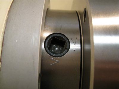
D1-4 Chuck Mounting

Radials

Registered
Registered
Joined
Feb 7, 2018
Messages
160
Hello,

I just finished a disassembly and cleaning of the 3 Jaw chuck on the new to me Enco lathe I purchased recently. The spindle is a D1-4 and doesn't have any makings on the spindle to indicate the tightening range on the cams. Looking at a grizzly manual for a comparable lathe it seems that the cam should rotate between 90 and 180 degrees to be in the tightened range? I've got two cams stopping at ~110 degrees of rotation and the third at ~160 degrees when tightening clockwise. The face of the spindle and the back of the chuck look good and tight, and I've got very low run out on a 1" ground test rod so I believe everything is aligned properly. My question is does the tightening of the cams seem correct degree wise? This is my first experience removing/ installing a D1 style chuck.

Thanks,
Nick
 
Yep sounds like you're good. I like to refer the position by hour hands. 12:00 would be disengaged. Properly tightened should be between 3:00 & 6:00. Just make sure you don't get AM & PM mixed up though. J/K of course. ;)

It would be a good idea to index your spindle/spindle accessory. Clock the chuck or whatever in all 3 positions & check runout. Choose the lowest reading, then mark the spindle & one of the cams. That way you can always put the chuck back on in the same position & it should repeat well. Some spindles may already be marked with a dab of paint or something.

I just put a simple center punch mark on mine.

Img_6643.JPG.jpg
 
Yep sounds like you're. I like to refer the position by hour hands. 12:00 would be disengaged. Properly tightened should be between 3:00 & 6:00. Just make sure you don't get AM & PM mixed up though. J/K of course. ;)

It would be a good idea to index your spindle/spindle accessory. Clock the chuck or whatever in all 3 positions & check runout. Choose the lowest reading, them mark the spindle & one of the cams. That way you can always but the chuck back on in the same position & it should repeat well. Some spindles may already be marked with a dab of paint or something.

I just put a sime center punch mark on mine.

Ok, I'll give the clocking a try and see if it gets any better/ worse in the other two positions. I like the idea of marking the chuck too for a known repeatable good position as there are no markings at all on anything.

Thanks!
Nick
 
I just got lost !! I have an Enco 14x40 sold as a D1-4 but only has 3 Lugs on it . The guys here saved me from disaster by telling me to put Layout dye on the spindle taper then mount and dismount my chuck. Using 400 grit emery cloth to remove the dye transferred to the chuck, repeating the process until the chuck stayed in place. This is my first encounter with the D1 mounting. I have used the lathe on random projects (probably less than 200 hours) and now find some run-out on a 1"x
12" test bar that I was going to check the tailstock alignment. Out of curiosity I stuck my pinky in 1 of the mounting holes to determine the correct rotation of the locking cam lobe. Turning the lobe counterclockwise seems like the correct way to secure the chuck onto the tapered spindle. Now I read that a fellow hobbyist turns his 4 lobes clockwise.

Like Radial's lathe there are no indexing marks on the spindle nor were the chuck lugs numbered so I haven't really got the indexing completed as described here. Got a lot of checking to do in the next few days.
Have a good day
Ray
 
I just got lost !! ... Out of curiosity I stuck my pinky in 1 of the mounting holes to determine the correct rotation of the locking cam lobe. Turning the lobe counterclockwise seems like the correct way to secure the chuck onto the tapered spindle. Now I read that a fellow hobbyist turns his 4 lobes clockwise.

Howdy, Ray.

The correct way to tighten each of the camlock retaining lugs is to turn them clockwise. There should be a line on each of these retaining lugs; positioning each one at 12 O'clock should allow the lugs of the chuck to slide into place on the spindle. Then each retaining lug is turned clockwise until it interlocks with the lugs on the chuck, securing the chuck in place so it doesn't fall off. Then you tighten each of the three retaining lugs clockwise until they are firmly snugged. The line on the retaining lug should be between 3 and 6 O'clock. If the line is not within this range, the depth of the lugs on the back of the chuck need to be adjusted in or out until the line on the retaining lug is oriented properly.

I am attaching something from Jacobs pertaining to the proper procedure.


Attachments

  • Jacobs on D1-4 chuck mounting.pdf
    35.3 KB · Views: 44
As long as the mark on the cam is between the two V marks all is good. I suggest going around a few times to snug up. I read somewhere years ago from a "master machinist" that you could just mount the chuck and crank the cams up. Try that with a dial gauge on a test bar and you will be surprised at how much run-out you end up with. You don't need to crank the hell out of the cams either. Righty-tighty, lefty-loosey. Make sure that the spindle taper, inside of taper in the chuck and the chuck backface and mating area on the spindle are super clean and then put a couple of drops of light oil on the faces.
Mark the outer of the spindle, the chuck backplate to match and at the same time the backplate and the chuck plus the jaw positions once you have found the best orientation as sooner or later you will need to strip your chuck down to clean it.
D1 mounting system is one of the greatest things since sliced bread I reckon.
 
The taper is a tight fit on my chucks so I make sure to pull the chuck onto the spindle as straight as possible. I first turn all the cams only to the 3 o'clock position. Then continue around turning gradually tighter while trying to close the space evenly until full contact.
I like the tight fit on the taper even if it makes the chuck a bit hesitant to be removed.
With practice you can feel when everything is home and locked up. If the chuck is on right there should be no adjustment possible by further tightening of the cams.
 
Last edited:
It is important to check carefully (use a light from behind) if the back plate (or chuck rear face for integral mounting chucks) seats completely to the spindle face all the way around when mounted. It is highly common for the fit of the spindle taper to the chuck to be too tight, and the chuck is then only being held by a tiny ring of contact between the spindle taper and the recess. It also means than when tightened down, the first cam will pull the chuck to the spindle face on that point only, and the other two will have air gaps at the spindle face. The chuck being tilted will cause the chuck to wallow around, tipped from being in line to the spindle axis, and will never be repeatable or very usable. Check for the problem, and if you find it, see some previous postings on how to fix it properly. It is VERY easy to end up with the chuck loose on the taper and/or not concentric. This is an important inspection, and repair if needed, for any D series tooling.
 
Amazingly, after I posted that, I finished troubleshooting and repairing a 8" Bison 4 jaw chuck, with an integral D1-4 mounting, for a friend. I went to test it on my lathe, which is also D1-4, and I cannot get more than one pin to engage with the cams at a time, and that is due to the spindle taper on my lathe will not letting it seat. It may have mounted to my lathe if I let off the pins one revolution each, but it still would have only been seating on the taper, not on the chuck face. I will have to take the chuck back to his shop and take a close look at his lathe before taking any action. I really hope someone did not trim the spindle taper on his lathe to fit the chuck... :eek 2: Well, I DID say in my post earlier this morning that THIS IS A COMMON PROBLEM! If you have a D1 series spindle on your lathe, you should take a very close look at how the chuck(s) fit the spindle and if they are registering on BOTH the spindle taper AND on the spindle face.

BTW, this is the first Bison chuck I have worked on, and it had some serious problems with fit from the factory. The tenons that guide the jaws were sloped high toward the chuck center equally on all three jaws, and required major effort to close the jaws. It is an older chuck, with zero other information on it other than the Bison badge inlaid in the face and 8/4 over 82 below the inlay. It must have been made on Friday evening or Monday morning, for sure.
 
Back
Top