I have been working on my version of the David Kerzel hit-miss engine. I took the plans from David Kerzel and redrew them in SolidWorks and made some changes to fit my machining style and abilities. The crank bearing blocks are one piece with oilite bushings. I made the crank shaft from pieces instead of trying to machine it from one piece of steel. I bought the gears from Mc Master Carr and machined them to size. The cylinder liner is cast iron. The piston is aluminum with an X-Ring for sealing.
I still need to make the valves and the valve seats, make the valve springs, finish the piston and the the head, make the cam, and build the carburetor. I have been looking at the drawings and I can not figure out how to make the cam. Any information would be greatly appreciated.
Below are some photos. I hope it runs when it is done.
You are doing an excellent job especially on the governor assembly and hit miss arm.
On my engine I cut the cam lobe on the CNC machine so no help here for the manually cut version.
Keep up the good work.
Ray:
Thanks for the kind words. I do not have the main housing machined to allow water to go all the way around the cast iron cylinder liner. Only a small top section is exposed to the water. Do I need to have the water go all the way around the liner. I was worried about leaving water in the cavity and causing rust.
I ran my engine yesterday for over 25 minutes as I wanted to seat the valves and break in a new piston o-ring I had installed. I did have water in the jacket with the highest temp reading of 110 degrees. For short runs I don't use water cooling but if you can easily remove the liner I would suggest cutting the cavity but that is up to you. After I use water cooling I just turn the engine upside down to remove the water and have not had any rust problems.
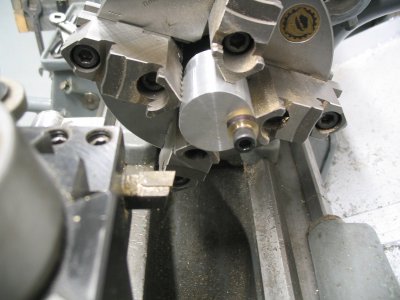
Well I figured out how to cut the cam. I looked further at the original drawings and made the blank and the jig. You lock the round cam on the jig and turn the side until it is .538". Then you loosen the mounting screw and index the cam clockwise a few degrees then take another cut. You continue doing this until you come back around and leave a .050" area that is not cut. It went very smooth. I had to file the OD to remove the steps. Attached are some photos of the process of cutting the cam and the finished cam.
Now I need to attach the cam to the drive gear.
Below is a photo of the top of the area with the cam and cam follower. In the other photos above the regulator arm was too close to the cam follower arm. I found that I needed to add .062" to the regulator arm mount. I did not have it mated to the bottom of the counter bore in the side plate. Now everything looks correct. The regulator arm is horizontal and it just clears the cam follower bracket. I might need to remake the bobbin that moves the regulator arm. The grooves are a little wide for the balls and there is some dead zone in the stroke.
Tomorrow I will chuck up the main housing and bore out a groove to allow the water to get all the way around the cylinder liner.
I have the valves made and I made the valve guides but did not drill the holes for the valves rods in the guides. I pressed the valve guides into the head and flipped the head over and clamped the head in the vise. I picked up the 3/16 holes holes in the head and drilled the holes for the valve rods and then used a 90 degree counter sink to cut the valve seat. I did this for both valves. I lapped the valves in the head using my electric drill and some lapping compound. I then checked the valves to see if they were seated and i can get the intake valve to hold about 30 psi but the exhaust valve will only hold to about 20 psi.
Ray I am thinking that the exhaust valve needs a little more work. What presure do you get to hold on your engines? How do you lap your valves?
I made a plate for the head to bolt to that had a recess for the valves and spark plug to fit into. I then added an air quick connect fitting to the back side of the plate so I could pressure it with shop air. When you can't hear any air escaping from the valves then dunk the whole assembly into a pail of water and that will show you where you need more work.
I spent the last few days making the valves, the valve guides and seating the valves. I first tried making the head like the plans called for and seating the valves in the head. I could not get the valves to seat properly. I talked to Ray and he said I should remake the valve guides and have the valves seat into the valve guides. I made a new head and new valve guides. I cut the seat with the same cross slide setting that i used to cut the seats on the valves. After lots of lapping I was able to get the valves to seat. I did not drill the hole for the spark plug yet because I need to get a spark plug and a 1/4-32 tap.
I am still waiting for my quad ring for the piston. It has been sitting at the post office distribution center in Cleveland for the last few days. When I get the quad rings i can finish the piston. Today I installed the wrist pin into the piston and connection rod. I installed the piston without the ring.
I still need to buy the ignition components . Tomorrow I will start on the carburetor.
Today I made the carburetor. The parts were small but I did not ruin any making them. When I pressed in the cross bar I looked at the drawing and it looked like the spray orifice should be up. The more I think about it I think the orifice should be down. I had a 50-50 chance of getting it correct. Ray, should the orifice be on the top or bottom?
There is not much more I can do until I get the ignition parts and the quad rings. I might start working on the base.
This site uses cookies to help personalise content, tailor your experience and to keep you logged in if you register.
By continuing to use this site, you are consenting to our use of cookies.