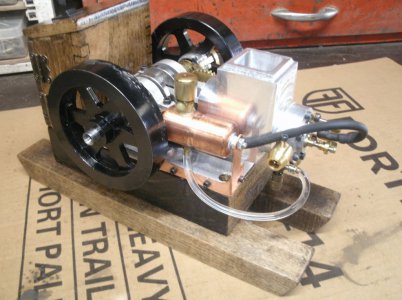
David Kerzel hit-miss engine

rdean

Active User
H-M Supporter Gold Member
Joined
Feb 2, 2014
Messages
1,059
I got the engine building bug around the middle of April during the lock down. I ordered a casting kit but it got lost in shipment and I just wanted to build something so I searched for a set of plans. I found the David Kerzel hit-miss engine and the plans were available free on the internet. David designed this engine in 2003 and many examples have been built. It is made from bar stock that many of us have in the bin or can get easily. I did not know at the time that the Chinese had copied this engine and were selling it around the world.

I used the plans as a suggestion and made many changes. The crank is on ball bearings, the ignition system uses a hall effect sensor, and the gears I made Module 1 as that is the smallest gear cutting set I had.
Many more changes and design features (mistakes) were added.

Here is a video that a friend recorded for me I hope it works.

Thanks for looking
Ray
Edit: Well it doesn't seem to be working so what am I doing wrong?
View attachment rays engine2.mp4
 
Last edited:
OK
I can't get the video to work so I know everyone likes pictures and I will add a little commentary as we go along.

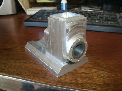
I started out with a piece of 5/8" aluminum for the base and a piece of 1 1/2" for the main body.
GEDC4345s.jpg

The cylinder liner is cast iron pressed in to the body and six cylinder head bolts 6X32.

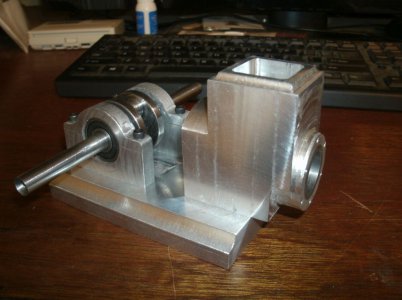
I made the crankshaft in one piece from round stock about 1 1/4" diameter.
The crank mounting pedestals are completely different from the plans but I wanted to use ball bearings on the crank. At this stage I didn't know how many design changes would be needed later on because of this change.
GEDC4348s.jpg


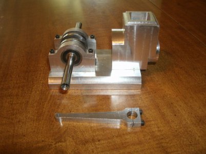
The connecting rod is made from aluminum also and I didn't add any bushings to the ends. I don't for see the journals wearing out any time soon as I am 71 years old it should last for me.
GEDC4354s.jpg

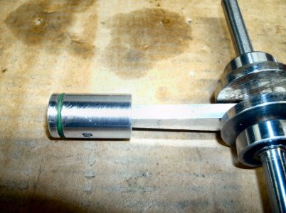
The piston is aluminum also with a diameter of 3/4". The high temperature o'ring serves as the piston ring.
The bore 0.800 and has a final compression ratio of around 6 to 1.
GEDC4365s.jpg

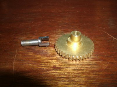
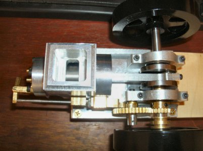
This is the large timing gear of 36 teeth and mounting stud I made. It also shows the cam lobe for operating the exhaust valve. The smaller gear has 18 teeth and both were cut using a module 1 gear cutters.
GEDC4374s.jpg

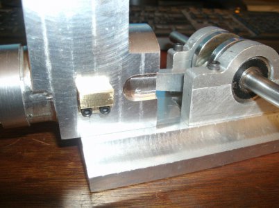
Here is where the trouble started. You can see the brass push rod block on the side of the housing. The push rod has to be in line with the center of the crankshaft or else many other problems arise. Because of the fact that I used ball bearings on the crank shaft the mounting location for the cam gear is now gone. It should be right in the seam between the main bearing cap and the mount. I moved the cam gear lower down and away from the bearing cap for a good location and will make changes to the push rod pawl that rides on the cam lobe to correct the offset.
GEDC4379s.jpg


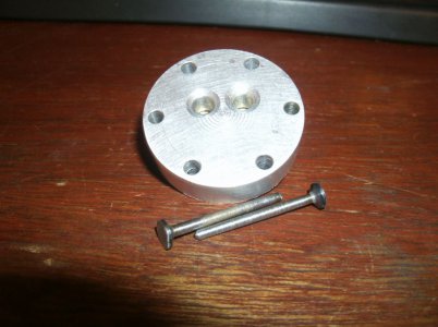
The cylinder head is aluminum also and the valves are made from some scrap steel I had around. The head would be later fitted with brass valve guides and seats as the original seats I drilled in the head proved to be unusable. I think I made a total of 5 valves before I got two I could use. The valve faces are 0.250 in diameter and the valve stems are 0.093 so you can see why I had so many failures.
GEDC4391s.jpg

I didn't intend to do a build thread when I was making this engine so I didn't document all the stages or show the operations. I hope this picture presentation is suffice.

That's all for now more later.

Ray
 
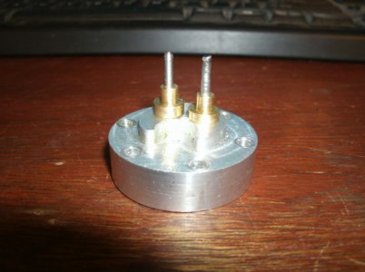
This shows the valve guides installed that I made for the head. It was much easier to keep everything aligned for the valves than trying to work from both sides of the head.

GEDC4393s.jpg

A top view of the timing gears, push rod, and rocker arm.

GEDC4388s.jpg

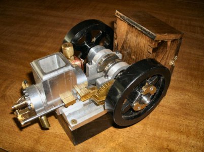
I made a outhouse on the back for the ignition system and batteries. The ignition system is made for a model airplane engine and uses a hall effect sensor to fire the plug. The governor fly weights can be seen mounted in the fly wheel. When the engine reaches a set speed the exhaust valve is held open until the engine slows some and then the valve is allowed to close which causes a power stroke or two to get backup to speed again.

GEDC4402s.jpg

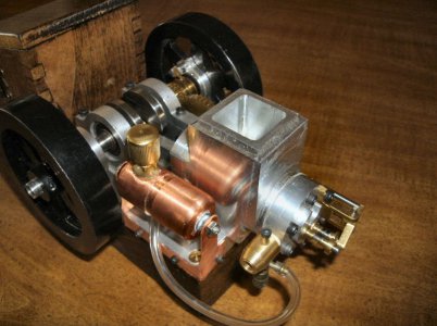
I made a gas tank from two 3/4" copper fittings soldered together and made a stand from copper plate for looks. The height of the gas tank makes a big difference in how the engine runs. Some people have made a check valve in the gas line to keep the fuel right up in the carburetor at all times. I designed the carburetor myself because I had read that the original design was not too reliable. It seems to work OK but should have had a finer adjustment range. Very easy to get too rich or too lean a mixture.
I wound the valve springs from piano wire using the lathe in slow speed and it turned out much easier than I had expected. The intake spring is the weakest spring you can make and still hold the valve shut as the intake valve is opened by vacuum from the piston going back and the exhaust valve closed..

GEDC4404s.jpg

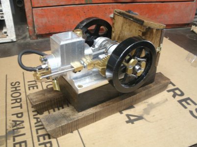
Here it is completed with the electrical system and a set of skids under it. When these engines were used on the farm for power many had skids installed so they could be moved around the farm by horses.
GEDC4436s.jpg

And the other side of the engine.
GEDC4439s.jpg

It does run very well (to my surprise) and starts fairly easily when cold and always on the first spin when warmed up.
The longest I have run it in one stretch is 17 minutes with cooling water and the highest temperature recorded was 117 degrees.

This was a new level of machining for me making so many small parts.
Hope you liked the thread

Ray
 
I am using Coleman fuel because it has few additives , burns cleaner and is very convenient in a quart can.

Thanks
Ray
 
Glad to see you finally got the video posted.
 
Back
Top