DC motor conversion. Flywheel or no-flywheel?

mike96

Registered
Registered
Joined
Aug 16, 2011
Messages
63
Been a while sense the last post. Things are starting to come together on my mill but had a quick question to ask.

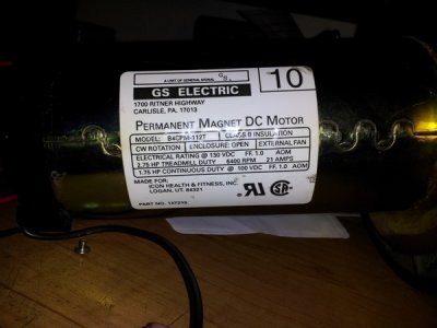
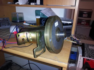
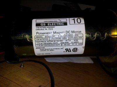
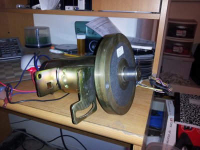
I am in the process of setting up a DC motor on my mill that I got from a tread mill and was curious... Should I keep the flywheel on the motor and make a new intermediate pully setup to help with extra torque or should I remove it and run just the motor and make a new pully to go straight to the mill head?

What would you do?
 
I would keep the flywheel myself. The additional rotating mass could make the difference on a long hard cut between success and failure. That extra bit of stored energy may really come in handy especially when turning slow. Just my opinion.
Bob
 
Every one I've seen is CI. There was at one time a manufacturer of exercise equipment here, and I quoted on reworking a quantity of them that came in from their importer with undersized bores. I quoted cheap, but still they went to scrap.
 
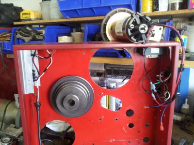
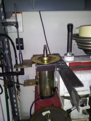
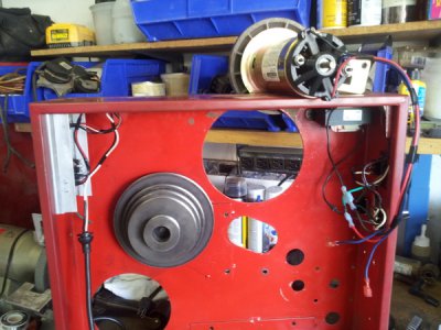
Yea this one is cast iron and fairly heavy... Problem it is giving me is that there isn't really a good way to bolt the motor down. I was thinking of using the flange under the flywheel and drilling a couple of bolt holes in it that way if I have to I can easily remove it but there isn't enough room to but a bolt in between the flange and flywheel. I could press it off cut a grove in the reinforcement fins on the back side of the flywheel and pres it back on. but if I get it a little lopsided I could potentially have a vibrating mess on my hands. I suppose I could just weld it and call it a day. I am going to the store after work tomorrow to pick up some switches and a pot so I can wire it up and make sure everything works then all I will have to worry about is mounting it and figuring out a belt setup.

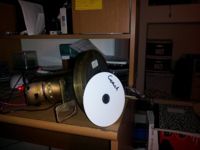
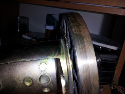
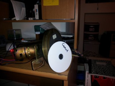
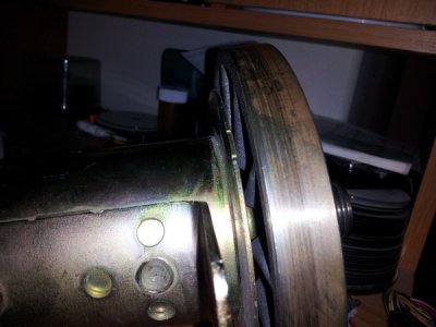
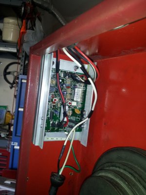
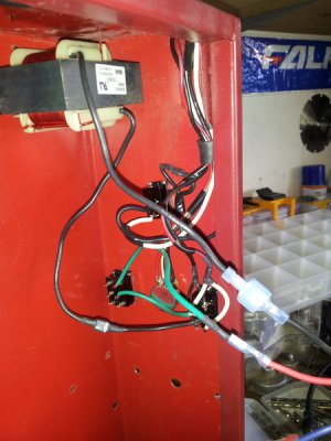
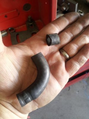
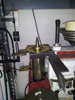
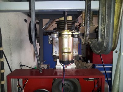
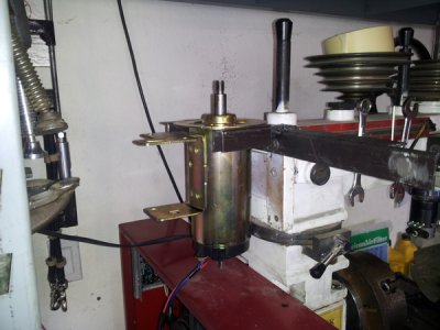
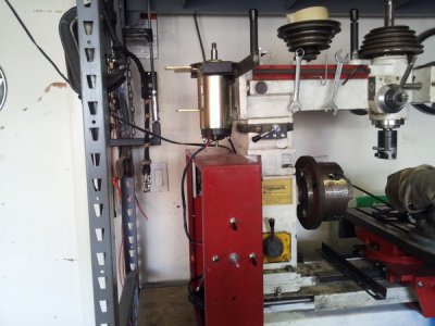
some pics to keep you all satisfied...

20120721_224857.jpg
20120721_224755.jpg
20120721_224817.jpg
20120721_224834.jpg

20120721_224857.jpg

20120721_224755.jpg

20120721_224817.jpg

20120721_224834.jpg
 
IMHO : the Flywheel needs to go, that "Extra bit of stored energy" Might get you though a cut or it might be enough to throw a work piece at your Mouth in a Bind. Sorry for the Negativity but, Seen that Movie and didn't like how it ended. (loosing a tooth at 3am) Just my Personal Humble Opinion
 
Looking at the second picture, it appears the threads are part of the flywheel, Is this so?

Also how is the original mount attached to the body, just spot welds?
 
Mike,

I have a fair amount of hands on experience with the TM motors having used them in some 8-10 applications. Presently have a drill press that has had one on it for 15yrs, and a band saw for 3 yrs, have had 3 lathes and 2 mills with one also.

First off, I have never used the flywheel - well thats not entirely true.. I usually cut the flywheel off down to the threaded portion to use it as a 'hub' in fashioning a usable means of driving. I will cut a keyway in this hub, or use a set screw, to prevent the thread from loosening if I am gonna be using reverse on the machine. A couple times I was able to use an acceptable existing pulley to bore out and slip over the 'hub' - other times I have cast a means of driving the machine. Usually it boils down to the particular machine as to the best/easiest method.

This also applies to adapting a means of mounting. That particular motor is about the hardest to fashion a mount for, the one I used I sawed those 'legs' off and fashioned a mount using a 'cushion' mount off an old motor in the scrap pile and tack welded to it. I have also done as you suggested and used the front flange to drill a couple holes in - as you noted, this probably wouldnt work using the flywheel.

Just a "for what its worth" note -- I have found that those motors vary widely in their performance, and there seem to be dozens of varieties. On one of the lathes I was adapting a TM motor to I had 2 motors that just would not perform satisfactorily, but with the 3rd one the lathe ran beautifully. Has a lot to do with the motor controller board too...
 
IMHO : the Flywheel needs to go, that "Extra bit of stored energy" Might get you though a cut or it might be enough to throw a work piece at your Mouth in a Bind. Sorry for the Negativity but, Seen that Movie and didn't like how it ended. (loosing a tooth at 3am) Just my Personal Humble Opinion

Thank you for the responce...Definitely taken into consideration.

Looking at the second picture, it appears the threads are part of the flywheel, Is this so?

Also how is the original mount attached to the body, just spot welds?

The end portion of the flywheel you are looking at isn't threaded but a finer toothed version of an automotive serpentine belt. Instead of having 4-5 ribs for a 1 inch wide belt this one had 7-8 ribs per 1 inch wide belt. And yes, unfortunately the large mount on the motor now is only held on by two large tack welds.

Mike,

I have a fair amount of hands on experience with the TM motors having used them in some 8-10 applications. Presently have a drill press that has had one on it for 15yrs, and a band saw for 3 yrs, have had 3 lathes and 2 mills with one also.

First off, I have never used the flywheel - well thats not entirely true.. I usually cut the flywheel off down to the threaded portion to use it as a 'hub' in fashioning a usable means of driving. I will cut a keyway in this hub, or use a set screw, to prevent the thread from loosening if I am gonna be using reverse on the machine. A couple times I was able to use an acceptable existing pulley to bore out and slip over the 'hub' - other times I have cast a means of driving the machine. Usually it boils down to the particular machine as to the best/easiest method.

This also applies to adapting a means of mounting. That particular motor is about the hardest to fashion a mount for, the one I used I sawed those 'legs' off and fashioned a mount using a 'cushion' mount off an old motor in the scrap pile and tack welded to it. I have also done as you suggested and used the front flange to drill a couple holes in - as you noted, this probably wouldnt work using the flywheel.

Just a "for what its worth" note -- I have found that those motors vary widely in their performance, and there seem to be dozens of varieties. On one of the lathes I was adapting a TM motor to I had 2 motors that just would not perform satisfactorily, but with the 3rd one the lathe ran beautifully. Has a lot to do with the motor controller board too...

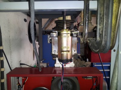
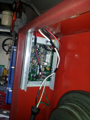
Thanks for all the input.. I picked up a MC60 speed control and a choke off of e-bay a few days ago. From my research this seems to be the most popular speed control for this type of application. As for mounting I think the flywheel will come off and I will turn it down so that I can add a v-belt pulley to it. This will also let me make it so that I can drill a couple of holes in the top flange of the motor and mount it that way. If done correctly I may even be able to adapt the mills factory pulley to the motor.

And with that... I am off to the bat cave... er.. I mean the garage... for wiring and welding.
 
OK, back from the garage and Holy Cr@p it is humid outside. I look like I just stepped out of the shower. This is Nevada it isn't suppose to be this humid here...

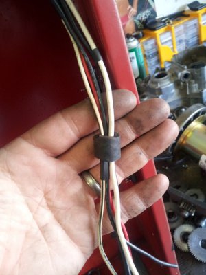
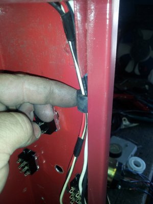
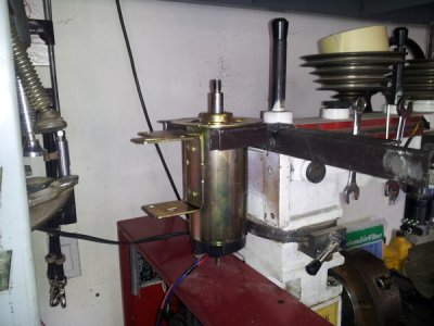
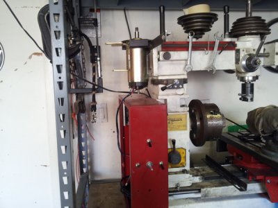
Any way,, got it all wired up and running. Although it took a little while. I thought I had a defective board for a bit. First it wouldn'tn power up even though when I switched it on and put a multi meter to the board I was showing about 115VAC at the connectors... So I started disconnecting things first the motor then the pot then I swapped over to a totally different power cord and "POWER"... Started working. So I started checking my switches and what not, turns out I was wanting to use the thermal switch in the motor as a safety... Yea it doesn't work, so I had to bypass it. I hooked every thing back up but still couldn't get any speed control. Again started disconnecting things and checking for 12V going to the pot. I was getting 12V but not when the wiring was connected. It took me a little bit to figure out that the controller didn't like the 12v computer fan I had hooked up to the power source for the pot. I had added it in for additional cooling... So I clipped the wires to the fan and I now have a DC powered mill. Well almost. I started on the bracket for the motor so I would say I am about 1/2 way done. Maybe later tonight or tomorrow, I want to add some 45deg brackets for stability and maybe something on the bottom or on the lower of the two stock mounts to help keep the bottom from wanting to twist out under higher torque loads.

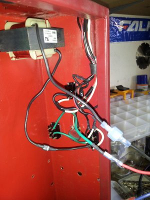
Switches are... Top one is master power. Bottom row on the left is forward/reverse. Middle is the speed pot. Right is for when I get around to swapping the lathe over to a DC motor also, I will be able switch the speed controller from the mill to the lathe and not have to worry about having to buy another speed controller, and pot, and reverse switch.... And have that many more switches on the front of the mill.

O - and,,,, November,,, Apperantly the flywheel threads onto the motor. So I guess it is threaded somewhere.

20120722_172119.jpg
20120722_172111.jpg
20120722_172127.jpg
20120722_132451.jpg
20120722_132510.jpg
20120722_132522.jpg
20120722_190502.jpg
20120722_190016.jpg
20120722_190008.jpg
20120722_190028.jpg

20120722_172119.jpg

20120722_172111.jpg

20120722_172127.jpg

20120722_132451.jpg

20120722_132510.jpg

20120722_132522.jpg

20120722_190502.jpg

20120722_190016.jpg

20120722_190008.jpg

20120722_190028.jpg
 
Back
Top