DC treadmill motor wiring info needed

Jericho

Active User
Registered
Joined
Aug 10, 2011
Messages
108
Not sure if this is the best way to get back to my DC motor situations but ...
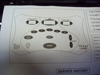
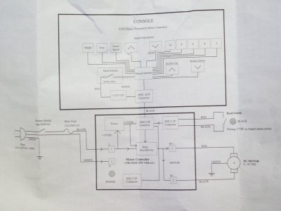
So I've gotten another treadmill motor this time with the electronic panel that controls the motor. Also have the control wire that formerly went to the operator panel but no operator panel. 6 colored wires and a green wire(total 7) are in a connector that looks similar to a phone connector. How does one determine the function of those wires so that a manual pot (possibly) or momentary buttons could be connected for speed control. Other functions on the picture of the operator panel seems to show several presets for speed, distance traveled ,time elapsed, and speed with a stop and + and - speed control. Any help even getting a direction to look would be appreciated.
 
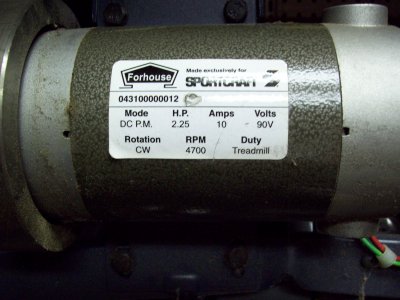
I am working on the same thing right now, take pictures of board & connectors, name & model # of board, picture of motor data plate.
I have some schematics of some treadmill boards.:biggrin:
 
I am working on the same thing right now, take pictures of board & connectors, name & model # of board, picture of motor data plate.
I have some schematics of some treadmill boards.:biggrin:


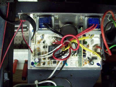
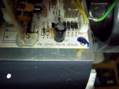
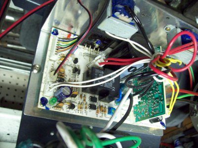
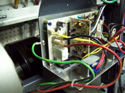
Hopefully this will show the pictures. Couldn't figure out how to do photobucket.Board # is partially hidden in photo but it's FH-3545C-PW-N. Original machine was a Sportcraft TX4.9 model.

100_0765.JPG 100_0766.JPG 100_0768.JPG 100_0769.JPG 100_0770.JPG 100_0771.JPG 100_0772.JPG
 
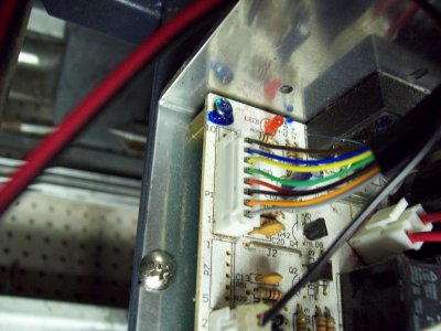
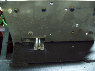
Fourth picture down is the control wire from the operator panel on the P1 connector.Metal plate picture has a couple of screws to pots on the other side I think.
 
Get your volt meter and clamp onto that green wire for ground, then take the red probe and file it down so that it will fit into the holes where those 7 wires enter the board. Now operate the treadmill changing the speed trying out each slot ( I would start on the left). There should be one that changes voltage, maybe like from 0-5 volts. 0 volts should be stopped. then try plugging a potentiometer (maybe a 0-10K pot??) using this wire. There is also the possibility that it uses PWM to control speed, like RC airplanes use. On that harness I am guessing that black and red are power, red could show like 12 volts, one of the others is power for a fan or something and two or three of the others are for speed control. The best way to figure it out would be to tear apart the console and see where each wire goes. Is it currently working?

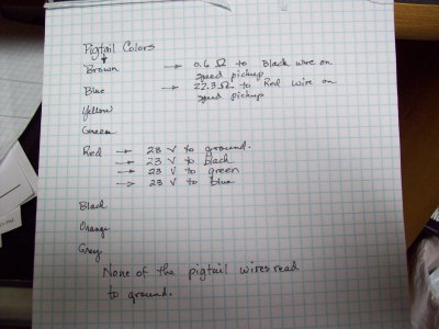
No, it is not currently working because I don't have the operator's control board portion of the machine which is where all the push buttons and microprocessor were located. This paperwork( attached pics) was in a plastic bag on the bottom of the treadmill when I took it apart and shows the options that WERE available and I assume the microprocessor controlled speed thru a feedback circuit from the speed sensor magnetic pickup on the rotating assembly drive roller. Wire harness from the operator panel terminates with a flat connector on the motor panel board with wire colors L to R of brown,blue,yellow,green,red black,orange and grey. They other red and black wire pair shown in picture 100-0770 is from the speed pickup. If these photos load you will see all I have so far. I will try and get the thing powered up as is and get voltage readings on all pins later today and post results. I'll pick up a pot at Radio Shack also for future use as I'll have to have one sooner or later anyway.Thanks in advance for all the input.

100_0773.JPG 100_0775.JPG
 
Here is the info I got from the pigtail wire leading from the operator board to motor board.

100_0776.JPG
 
OK,I wont bid on it then.I was going to buy it for a backup if you did not want it.I hope you get it.
Bill L.
 
OK,I wont bid on it then.I was going to buy it for a backup if you did not want it.I hope you get it.
Bill L.

I skimmed over the manual . What other components have to be gathered for it speed controls for controls? I seem to remember some mention of plug in resistors depending on motor size.I'm being a bit lazy about reading the whole thing because it seemed a little overwhelming. I'm still wanting to make the one I have work but this is my second venture into run what you have stuff. Learning as I go.
 
Back
Top