- Joined
- Jan 21, 2013
- Messages
- 863
Since there are others here that are learning Fusion 360 as I am, I thought this might be interesting. This is just how I solved a particular problem and may not be the best or correct way, but it works and I think it's pretty cool to be honest.
Since I'm designing a belt grinder to attach to my bench grinder's right side, I need a way to determine the spacing of the pulleys. How high does the top pulley need to be, and where does the idler pulley need to be. And here's the kicker: Let's figure out these numbers for different lengths of belt.
There is a website (in fact the only one of it's kind I've found) that shows how to solve this question for any arrangement of 3 pulleys.
I converted this into an Excel spredsheet so I could punch in the distances between the pulleys, and it would display the resulting belt perimeter, or belt length that would fit. I'll attach the spreadsheet for anyone that want's to try it out. Note that the sheet is locked to keep you from accidentally changing the wrong cell, but it's not protected, so you can unlock it to see the equations or make edits if you want to. Rename the extension to ".xlsx" I had to change the extension in order to attach it.
I'm over-engineering this drawing in order to learn more about the CAD system, and one of the things I learned was the use of parameters.
Here's a pic of the parameters that I have so far:
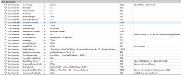
I can make a change to these values and have them instantly be translated to the design without having to do any editing. The drawing or 3D model just transforms to reflect the changes. This means that I can change the diameter of the drive wheel, and the length of the tension arm extends or shortens so that the tension pulley's face is parallel to the face of the drive pulley. I also can make changes to the distance the Idler pulley is placed behind the tower to allow for different belt lengths. Now I just need to see what happens when I make these changes.
To do this I made an assembly called "belt length calculations" that contains a sketch showing the right side of the machine. Using this, I can add dimensions to show the distance between each pair of pulleys. Because the pulleys are fully defined, these dimensions are "driven" and only reflect the actual lengths being measured.
Here's an example of the original design with a 4" drive pulley and a 42" belt. You can see the 3 distances being displayed.
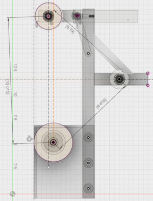
After talking to people here, I decided to change to a 6" drive pulley. All I had to do was change the drive pulley parameter to 6 and then plug the dimensions from the drawing into the spreadsheet. I can leave the drawing open (edit sketch) and make changes to parameters and see their effects right away. By playing with the distance of the Idler Pulley, I found that with a 6" drive, I didn't even need an Idler as seen here. Even this offset would require a 42.5" belt, so I'd be better off extending the tower and not bothering with an Idler at all.
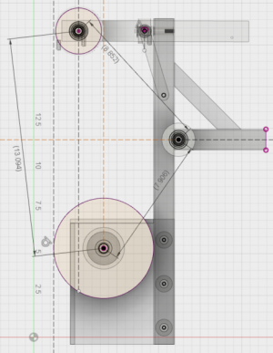
Ok, that's great! Now I can go to a longer belt. A little more experimenting showed that a 48" belt would work fine.
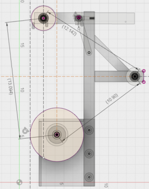
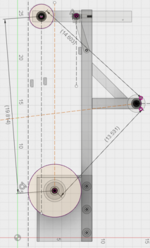
I could even go to 60" by raising the tower up to 26.25 inches. I'll probably do this as the longer belt should stay cooler and last longer.
Anyway, I hope this helps anyone else wanting to learn about parameters or figuring out belt configurations!
edit: oops, I changed the spreadsheet to make it easier to use, and didn't change the sum to suit. Fixed now.
Since I'm designing a belt grinder to attach to my bench grinder's right side, I need a way to determine the spacing of the pulleys. How high does the top pulley need to be, and where does the idler pulley need to be. And here's the kicker: Let's figure out these numbers for different lengths of belt.
There is a website (in fact the only one of it's kind I've found) that shows how to solve this question for any arrangement of 3 pulleys.
I converted this into an Excel spredsheet so I could punch in the distances between the pulleys, and it would display the resulting belt perimeter, or belt length that would fit. I'll attach the spreadsheet for anyone that want's to try it out. Note that the sheet is locked to keep you from accidentally changing the wrong cell, but it's not protected, so you can unlock it to see the equations or make edits if you want to. Rename the extension to ".xlsx" I had to change the extension in order to attach it.
I'm over-engineering this drawing in order to learn more about the CAD system, and one of the things I learned was the use of parameters.
Here's a pic of the parameters that I have so far:

I can make a change to these values and have them instantly be translated to the design without having to do any editing. The drawing or 3D model just transforms to reflect the changes. This means that I can change the diameter of the drive wheel, and the length of the tension arm extends or shortens so that the tension pulley's face is parallel to the face of the drive pulley. I also can make changes to the distance the Idler pulley is placed behind the tower to allow for different belt lengths. Now I just need to see what happens when I make these changes.
To do this I made an assembly called "belt length calculations" that contains a sketch showing the right side of the machine. Using this, I can add dimensions to show the distance between each pair of pulleys. Because the pulleys are fully defined, these dimensions are "driven" and only reflect the actual lengths being measured.
Here's an example of the original design with a 4" drive pulley and a 42" belt. You can see the 3 distances being displayed.

After talking to people here, I decided to change to a 6" drive pulley. All I had to do was change the drive pulley parameter to 6 and then plug the dimensions from the drawing into the spreadsheet. I can leave the drawing open (edit sketch) and make changes to parameters and see their effects right away. By playing with the distance of the Idler Pulley, I found that with a 6" drive, I didn't even need an Idler as seen here. Even this offset would require a 42.5" belt, so I'd be better off extending the tower and not bothering with an Idler at all.

Ok, that's great! Now I can go to a longer belt. A little more experimenting showed that a 48" belt would work fine.

I could even go to 60" by raising the tower up to 26.25 inches. I'll probably do this as the longer belt should stay cooler and last longer.

Anyway, I hope this helps anyone else wanting to learn about parameters or figuring out belt configurations!
edit: oops, I changed the spreadsheet to make it easier to use, and didn't change the sum to suit. Fixed now.
Attachments
Last edited:

