Dividing a circle by 359

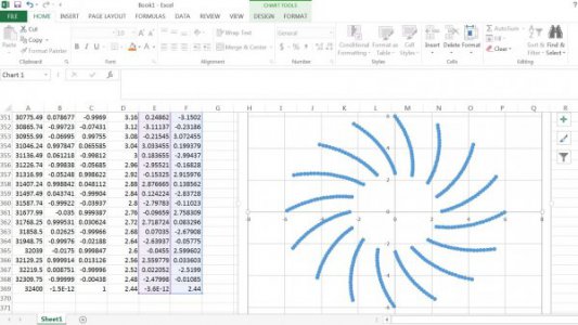
I played with this just a bit in excel. Here's what the spiral plate would look like if you started at 6" radius, worked your way in, then pulled back every 90 holes. obviously this is too big a plate. If you really want to do this, make two plates, one for the first 180 holes, then one for the last 179 holes. then you could get the size down.

change the file extension from .txt to .xlsx to open in excel


Capture.JPG
 

Attachments

  • dividing head.txt
    65.5 KB · Views: 12
Last edited:
This sounds like a "hypothetical" problem to me. For anything short of "Babbage's engine" I would be looking into staged / multiple gearing. From a practical perspective, I do most of my work from a BC (before computer) perspective. But then, I am a hobbyest in the purest sense. The above looks like the optimum solution. With any prime number, a dividing plate will need to be generated. (above 97) I would use, but not recommend, stepping it off with a dividers and keep plugging away until it was within reason.

That's the hard way so I don't recommend it. The next step would be to use a piece of drafting / graph paper. Measure off 10 spaces, divide by 10, and then extrapolate that number to get diameter. Then, using the graph paper, mark each point and draw a line to center. Determine the hole spacing desired and draw a circle. Punch each intersection and there it is.
 
To recap the method I'm familiar with - I have a rotary table with a ratio of 90:1 and a collection of standard dividing plates and assuming for a moment, I want to divide a circle by 7, with a reduction of 90:1, I would divide 90 by 7, writing the remainder as a fraction. which in this case would be 12 and 6/7, multiplying the fraction by 7, we get 42 / 49. or, 12 turns on the wheel and 42 positions on a 49 hole dividing plate.

But what about a number of divisions that's much larger, in this case 359? as I understand it I would need a dividing plate that's a multiple of 359. Further looking at what I have, if we take the 1 degree and and divide it by 30 (30 degrees of hand wheel movement per degree on the table) you end up with .033 degrees of movement per degree on the hand wheel, which gives us 348.387 which doesn't work. Does anyone have any suggestions as to how to divide a circle in 359 even parts?

EDIT: I realize that 359 is prime. which means there will be no ratio that will perfectly divide the circle, but I'm looking for help to get close enough. One possible solution is to gash it very lightly, make a hob and hob the gear, if the size of the blank is correct I should end up with the required number of teeth. but anyway, I would appreciate your input.

Thanks!
E
Why 359 t
 
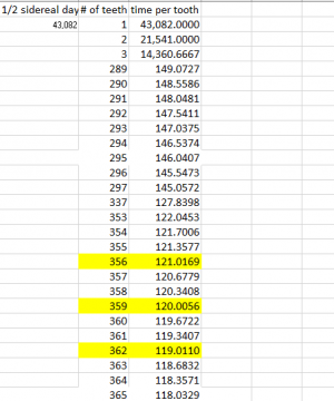
It could be viewed as theoretical. When the table was calculated, 359 offers a solution which is the most accurate (smallest error) there are other possibilities, I have attached a screenshot and the working excel file. I don't think I'll be creating a babbage engine though :)

After finding the attached solution, I set out seeing how others' deal with dividing a circle where you have a large prime # (or a number that doesn't work out on the standard plates) which brings me to my original post.

362 and 365 t would be the next choices, I think. these too would require a new dividing plate with a multiple of 181 and 73. I'm not sure this is any less work than 359 and the same goes for 356.

From a purely execution standpoint, 360 t is dead simple and 365 t (73 hole dividing plate is a lot more manageable than having multiple or a really large dividing plate.


Capture.PNG
 

Attachments

  • sidreal_calc.xlsx.txt
    21.6 KB · Views: 4
Sorry, I got called away for a minor emergency. To continue:

I got my hands on a set of fraction plates a few years ago (misidentified, not stolen) with prime numbers up to 97. They are well over a foot(16") in diameter and my indexer is 4 inch diameter. I leave the results to your imagination. It ain't pretty .... For any large number like you are describing, keeping track of minutes and seconds would be a real PITA. One missed second on tooth 345 and the job is botched and ready to start over.

Once you figure out the desired ratio of two gears, it would be like a clock mechanism. Multiple stages if applicable. A damn fine tooth if multiple stages won't work. That's where the hand derived plate comes in. Figure 359 ticks, like 1cm on a yardmeter stick..... Naw, thats only a hundred. Make it 1 mm per. So every 10 mm, mark a reference, and then divide by ten to get an accurate 1 mm.(0.03937) Now from that calculate the diameter of a circle. With a circumference of 359 mm, the diameter would be around 5 inches. Make a sunburst pattern, scribing out to a usable size and draw your circle. When you're ready to cut, each gear is marked. After making a half dozen teeth, set up an indexer for the rest. Simple but exhausting. But it can be done. Just have a big coffee pot. I would start with a hacksaw and a fresh pack of smokes, and a clear ashtray. For a larger gear, a cutter.

Once the first one, a master, is made, the rest are a piece of cake. The first concept to grab here is that an indexer or rotary table is not vital. As in, how was the first ever gear ever made? What is vital is to think through the problem and determine the simplest way to accomplish the end result. I play with model trains. They use a worm and pinion gear for the drive mechanism. I understood a worm and pinion when I was a kid. Simply a small indexer when you come dowm to it. Not really relevant, I had to plug the models. An indexer is fine for a production shop. But for one off gears with an odd number of teeth, as much time is spent figuring out how to make tham as the making. KISS

Bill Hudson​
 
Keeping it simple would be the best... but if you really need a 359 division plate, I think it can be done in a 6 inch diameter. If you run six tracks with 60 holes, 59 on the last and drill the holes so that each track was the position of every fifth hole (5 degrees and 50.14 arcseconds, it will fit! The trick is you turn one full turn plus a little over 90 degrees (angular distance of five "teeth" on dividing plate which makes the correct amount for five "teeth" on the gear. The sector arms are set to the 90 plus a fraction. When you get ready to do the 61st position, you will have to move the stylus to the next track. If you want the excel sheet with the coordinates, etc, let me know.
 
I would use compound indexing
Simple to use and use your rotay table or indexing head. With indexing plates.

It machine gear with higher tolenent that CNC

Dave

To recap the method I'm familiar with - I have a rotary table with a ratio of 90:1 and a collection of standard dividing plates and assuming for a moment, I want to divide a circle by 7, with a reduction of 90:1, I would divide 90 by 7, writing the remainder as a fraction. which in this case would be 12 and 6/7, multiplying the fraction by 7, we get 42 / 49. or, 12 turns on the wheel and 42 positions on a 49 hole dividing plate.

But what about a number of divisions that's much larger, in this case 359? as I understand it I would need a dividing plate that's a multiple of 359. Further looking at what I have, if we take the 1 degree and and divide it by 30 (30 degrees of hand wheel movement per degree on the table) you end up with .033 degrees of movement per degree on the hand wheel, which gives us 348.387 which doesn't work. Does anyone have any suggestions as to how to divide a circle in 359 even parts?

EDIT: I realize that 359 is prime. which means there will be no ratio that will perfectly divide the circle, but I'm looking for help to get close enough. One possible solution is to gash it very lightly, make a hob and hob the gear, if the size of the blank is correct I should end up with the required number of teeth. but anyway, I would appreciate your input.

Thanks!
 
That's awesome, thank you. I hadn't considered compound solution at all.

Keeping it simple would be the best... but if you really need a 359 division plate, I think it can be done in a 6 inch diameter. If you run six tracks with 60 holes, 59 on the last and drill the holes so that each track was the position of every fifth hole (5 degrees and 50.14 arcseconds, it will fit! The trick is you turn one full turn plus a little over 90 degrees (angular distance of five "teeth" on dividing plate which makes the correct amount for five "teeth" on the gear. The sector arms are set to the 90 plus a fraction. When you get ready to do the 61st position, you will have to move the stylus to the next track. If you want the excel sheet with the coordinates, etc, let me know.
 
Maybe this will be helpful to everyone wondering why 359 t?

I am interested in tracking celestial object and taking pictures of them. In Astronomy, sidereal time is used to locate objects in the night sky & a general explanation can be found here. To track an object in the night sky for long periods of time (over a few minutes), we need to be able to match the rotation of the earth vs the stars. In order to do that we need to find a ratio that will allow a motor to spin at a constant speed and enable us to cancel out the rotation of the earth.

There's a few avenues to go, one is to buy a commercial mount (prices here to rotate 30lb of gear are easily north of 2000$ CAD, but the popular mounts are easily 4k) as well as auto-guiding systems (mounting a scope on top of a scope with an additional camera and the images are fed into some software to compute drift, that in turn is used to adjust the speed of the motors.)

For the diy crowed, there's options here as well, from retrofitting an existing mount with commercially made gears like these and these and finally and of course, if you like pain (or just enjoy the process), you can try your hand at doing it yourself. This approach is unlikely to be any cheaper than buying off the shelf parts, but, where's the fun in that? And, after reading the linked the post, I think it's very achievable to do in your own shop.

Coming back to the 359t gear, when we look at the number of seconds (rounded) in a day, the 359 t gear offers the least cumulative error per tooth than any other gear with a reasonable number of teeth and diameter. By extension, the less error at this stage, the less reliance on other solutions like auto-guiding.

Thanks everyone for your input so far!
 
So, you want a worm drive with Zero backlash??

There is a method to use a worm cutter to hob out the large gear and then replace the worm with an identical one. You make both worms at the same time so they are the same. The large gear is allowed to spin free while cutting so the home shop machinist can easily do this. I remember reading about this and have seen pics of others doing it, but have no actual experience.

I'd suggest you research this idea a bit.
 
Back
Top