DIY knee mill build

Diecutter

Registered
Registered
Joined
Dec 19, 2018
Messages
176
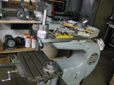
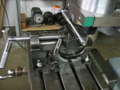
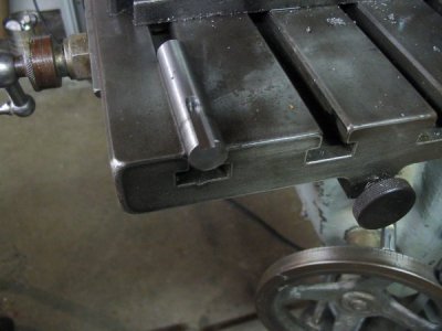
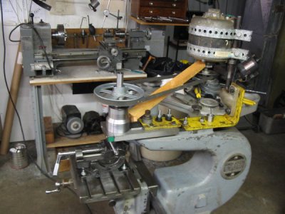
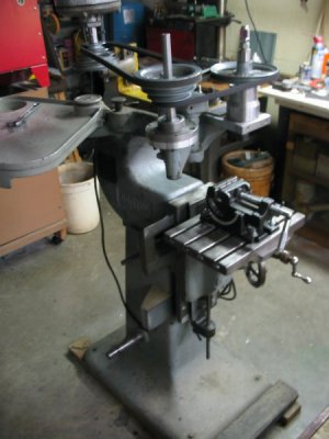
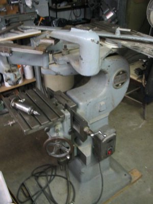
Since joining H-M this week some members encouraged me to post photos of my ongoing conversion of a Gorton 3-U pantograph into a knee mill. I have some machine shop experience, but none in building or operating a mill. More photos and narrative will follow as the build progresses. I don't have the posting skills yet as you can see, but I'm sure you get the idea.002.JPG002.JPG016.JPG017.JPG019.JPG008.JPG001.JPG
 
Interesting idea. Following. Tell us more about how you are designing the spindle. I know that can be a complex topic.
Robert
 
Interesting idea. Following. Tell us more about how you are designing the spindle. I know that can be a complex topic.
Robert
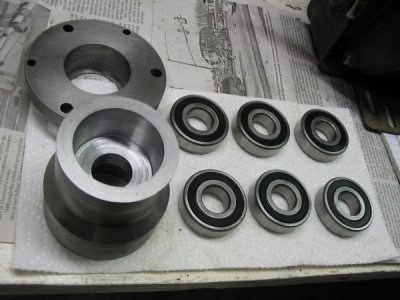
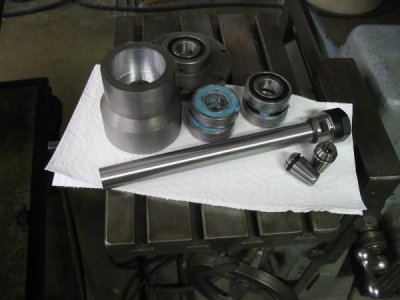
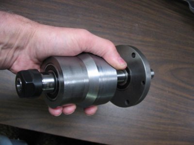
My designing is not too complex; collect a couple likely parts and convince them to play nice together. The spindle housing is 3" dia. S-7 die steel machined to accept four 6204RS 20x47mm deep groove bearings. The housing supports an ER-20 collet holder with a 20mm shank that is 200mm long. The ER-20 holder accepts up to 1/2" dia. cutters, and it's shaft is 20mm dia. (.7874" dia.) which should be plenty strong for an under one hp motor. Did I mention that this is going to be an economy build and that all the parts were in my scrap pile except the ER-20 holder which set me back $ 15.68 delivered from china.? So far lady luck is shining on me; The collet holder was of excellent spec. and quality, and the concentricity of the finished spindle assembly appears right on. I'm thanking my Jet 9x20 lathe for that. So under $40 cash spent so far on collet holder and collets, and I have a motor and enough pulleys to complete the drive (if I steal a step pulley from my Gingery lathe). Better get back to work so I can post more photos.
 
Do you have to preload the bearings to eliminate end play? How do you deal with end play?
Robert
 
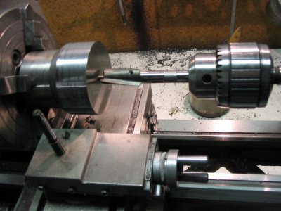
Thanks for the pictures. What kind of cutting tool is that in the next to last photo that is mounted in a drill chuck?
 
Do you have to preload the bearings to eliminate end play? How do you deal with end play?
Robert
The bearings used are deep groove ball bearings which is what I had on hand (read free). They don't appear to have axial play, at least not yet! I have a couple dozen of them, so if they start to go, I'll put in replacements and thread the spindle shaft for adjustment. Now that you mention it, my cnc 3D engraver has an Enco (lathe) headstock with smaller versions of the same type of bearing, and has an adjustment nut, so I may indeed have to thread the shaft. Alternatives are installing a small taper-lock two part pulley, or switching to tapered bearings (read auto wheel bearings) plus threading the shaft if it comes to that. Thanks for the observation.
 
Thanks for the pictures. What kind of cutting tool is that in the next to last photo that is mounted in a drill chuck?
You have a good eye. That tool is a Cleveland high speed steel 3/4" counter-bore with a 1/4" pilot which I got in a box lot at auction long ago. It's supposed to be used to cut the pockets to recess cap screws. To bore the housing, I drilled a 1/4" hole, then cranked the c/bore tool through using the tail-stock wheel prior to using a boring bar. It was fast and had very little chatter.
 
That tool is a Cleveland high speed steel 3/4" counter-bore with a 1/4" pilot
now I see it. I don't own any counterbore tools because I can cut counterbores on my CNC mill with a standard end mill. Nice way to enlarge a hole for boring bar clearance.
 
Just a short update on my DIY knee mill build. I'll post again with more photos after completing the initial build by this weekend. (hopefully).001.JPG shaft.JPG
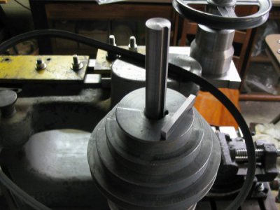
005.JPG This is a photo of the temporary linking of the motor directly to the spindle to cut a key-way for the two step pulleys to be mounted to the shaft between the motor and the spindle. Note the scrap of wood wedged between the spindle housing and motor housing to provide tension. Above that is a closeup of my first object cut with the mill; a 3/8" key-way on a scrap piece of shafting. I think this machine may turn out ok. I know I'm thrilled. The third photo is of the setup for the milling of the actual key-way to secure both step pulleys. It will be one continuous cut. More later as the build nears completion.
 
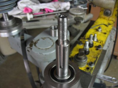
Just about have my DIY knee mill build finished, and it is under power and has already cut some key-way slots, keys, and threading of the spindle shaft (threading was on the lathe) for bearing adjustment. Thanks to rwm for the threading suggestion. threading.JPG
keycloseup.JPG
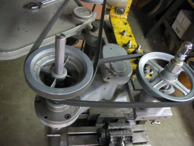
The pulley is a double reduction step pulley set-up as suggested by derf.pulleys.JPG
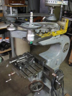
Here are a few views of the completed, running mill. I still have to refine it somewhat and slowly make upgrades as time/money allows. All but the spindle (a 200mm ER20 extension collet ) and a v-belt were parts from my junk pile. Happy to answer any questions.

right.JPGleft.JPG
 
Back
Top