- Joined
- Mar 26, 2018
- Messages
- 2,724
Chip load is often recommended by tool manufacturers and can be extrapolated to those tools that are not provided with cutting data.
Chip thickness is determined by tool geometry, coolant method, and material properties of the workpiece.
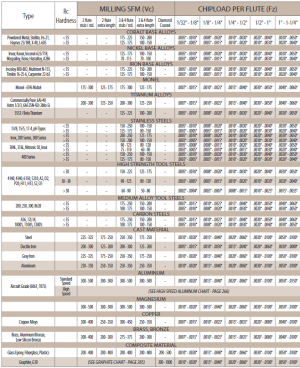
Here is the chart by Garr Tool which I often reference. These chiploads are usable for both carbide and HSS, but the Surface Speed (SFM) is specifically for carbide.
Use the columns on the right, selecting your tool diameter at the top. When choosing cutting parameters, I usually start at the lowest end of this spectrum and step up from there. But again, I have a small machine and those using large equipment can push these numbers harder.
Chip load is usually thought of as independent of other cutting parameters. Chip load and Surface Speed (SFM) determine spindle speed and feed rate for a given tool. Then WOC and DOC are chosen based on the type of cut needed and available horsepower.
Try punching these numbers into a speeds and feeds calculator (https://www.custompartnet.com/calculator/milling-speed-and-feed) and see how they get you the cutting data you need. Try bumping numbers up and down to get a feel for what affects what.

Last edited:

