JimDawson asked me a while ago to post up my CNC conversion. it's still a work in progress fraught with disasters of one thing or another. So I will try to post up what I can, it's also posted up over on the zone so if I miss some info you might find it there.
So lets see where did we start. lets go with the motor:
The Zx45 and I am sure many of the other clones are a bit bastardized in the specifications. I summed it up like this over on the zone: "so you have a D90 series B5 flange with a D80 shaft, and somewhere according to the Chinese 71 framing on the internals.
Now I understand why most seem to abandon it all and just go belt drive."
1500 RPM, sorry I tend to be a bit of a Tim Taylor more power kind of guy so......
I ended up buying this 3 phase Leeson motor which apparently can't be found anymore. I also purchased a Huanyang 2.2Kw VFD on ebay to power it.
a big downside here was I had to turn down the shaft of the motor in order to fit the head of the mill. it was either that or a belt drive and since I don't have a lathe this was even less of an option. I don't have any pics of this operation but it was an ugly hack job to begin with due to my lack of experience. what I did was took advatage of the side mount my motor came with to clamp it to the table like a 4th axis. my choice of turning tools however was complete crap. I wound up using a boring head and boring bar mounted in the spindle to do most of the cutting. this is not ideal FYI, the biggest issue is the boring bar likes to move since it is threaded onto it's arbor. Ideally if I were to do this over again I would come up with some sort of tool post on the side of the head. I may do this in the future anyways since I plan on running a 4th axis later on.
more stuff. well I bought a bunch of servo drives and had no clue what the hell I was doing. this can make things interesting. I made it work but it is a bit of a headache in doing so. I found these AMC Analog servo drives and thought: "Hey those will work and cheap too" well cheap can come at a price. Many analog servo drives you find on Ebay or some of those odd ball sites are Trapezoidal commutation, basically its a square wave of sorts. if you saw it on an oscilloscope you would see the slow rise and sudden fall and think hey a trapezoid. This is actually a very old school method of commutation because it relies on Hall sensors to detect where the motor is. Newer servo systems use a sinusoidal wave form. The motors are even wound slightly different and mixing them will result in a loss off 40% of your power at a minimum. sinusoidal wave forms look like your typical wave form we all have seen on TV and pictures it's that nice sweet curved up and down. Basically the drive uses the powered down lead to detect which coil has just fired off and fires off the next lead. As a result you have less wires but often choose to have encoders mounted to the motor to improve commutation accuracy. Alright enough of the science lesson what are we going to do about it.
I started hunting down motors that had hall sensors. I wanted to avoid brushed motors for a few reasons. I hate brushes like no other, They are dirty after running them for a while, they can erode the Stator after a while causing permanent damage, they are also less efficient. Really the only plus is they are cheap to purchase. So needing Hall sensors you have one choice DC Brushless Servos. but not just any BLDC motors come in two forms Trapezoidal or Sinusoidal. obviously we need the former. the first two were easy I found two ABB Servos and they were advertised w/ hall sensors. they were even within a decent torque range although I had to do some serious research on my conversions since they were not listed in-oz but as Nm. they were also rated for 3,000 max RPM so with a 2.36:1 gear ratio they would be plenty stout motor for the table.
I needed two more motors and this was the tricky part because I spent months searching until I came across two ALLIED MOTION EMOTEQ QB03402-B06-HE motors. these things have hall sensors and encoders. talk about killing two birds with one stone. although pricier than the ABB motors and 1000 rpm slower they had about .5 times more torque than the ABB's.
For the RF45 clones you want around 850 oz-in torque for the table. a bit more for the Z axis. Although with offsetting the head weight that's not as much of an issue. if you manage to neutralize it completely you might be able to use a smaller motor I have heard of people using Nema23's on this thing.
ok so next which recently I discovered is another thorn in my rear end is Encoders for the Table. at the time I opted for rotary encoders on the motor or possibly on the ball screw, I was undecided. in hindsight linear would have been better but my desire to make things more precise than physically possible I suppose was overwhelming. looking at the allied motion motors they were 2" disks with 1000 line count and Index. well the ABB's were a tad narrowerand a 2" disk was not going to fit under that hubcap in the back. plus I had to extend the shaft on those just to mount the encoders.
again not many photos of this process
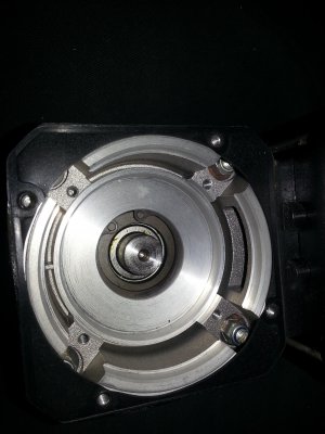
so I purchased 1" E5 encoders with matching specs to the allied motors. apparently they also came from US digital so I sucked it up and sent them almost $200. I had to extend the shaft, and I had to modify the back half of the motor shell to mount the encoder base. I used some aluminum disks I made using the spindle as a lathe and enlarged the hole where the motor leads go through (I still have to do this for the other motor so maybe I will upload some pics of that one when do it).
EDIT: I forgot to mention the encoders I got from US Digital apparently don't work. I'm waiting on a response from them about an RMA ticket, the odd thing it was both of the encoders I purchased with the exact same fault. defective? I hooked up the Allied motors to the same connectors and had no issue with them so I found it odd.
Moving on.... did you ever think CNC would be an easy process... ondering:
honestly the easiest part. Buying the computer... the hard part of that however is cramming all these electronics into some sort of a box. I went with a GIGABYTE GA-H81M-HD2 motherboard with 4GB ddr3 and a pentium G3220. I even found an Acer touch screen although that has some quirks of its own. I went the server rack route for mounting all that stuff and here is where wild ideas and bieng cheap get you in trouble. the server case I got was too large for the server rack that I bought funny considering it was advertised as super short and what I get was full length. I wound up shopping that sucker and reinventing the wheel in order to get it to fit the rack. downside which I will have to fix later is there is no front panel covers for the server case. I had to re orient the drive bays and the old front panel just won't fit as a result.
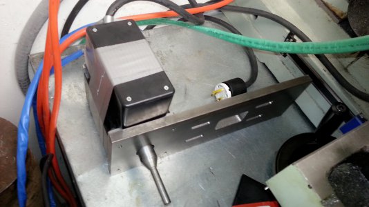
it's still a work in progress but here is my wiring nightmare.
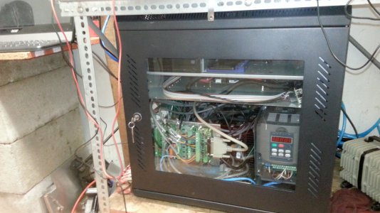
Eventually I will have an actual estop, start/stop/ MPG encoder wheel, jog speed selector switches, etc... mounted up with the touch screen
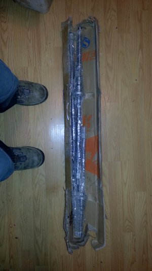
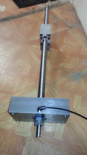
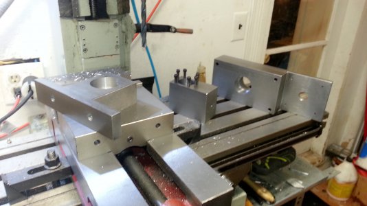
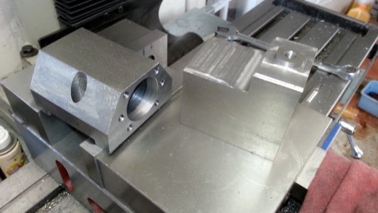
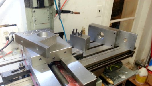
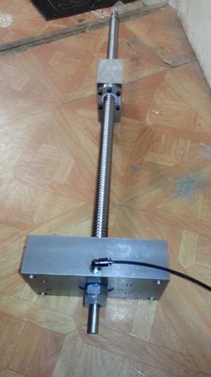
So back to some actual metal work. I wanted to build things as stout as possible with the motor mounts and ball screws. none of this is mounted on the mill yet and honestly if you can do some of this work on a friends mill or even at your employers if he/she is gracious enough I would highly encourage it. I am a bit of a lone wolf so that doesn't happen much. I ordered a 2505 ball screw with double nuts as well as two 2005 doublenut ball screws for the table. Sizes here vary greatly depending on the clone. Even the zx45's have a wide range of models and varying table and column sizes as a result. I ordered them from Chai at linearmotionbearings2008. he has a yahoo email address and if you order via email they are cheaper. but again you get what you pay for. His company does a good job for what it's worth, but they can't pack a box to save their lives.
hmm I can't upload anymore pics on this post it seems, ok next post.


So lets see where did we start. lets go with the motor:
The Zx45 and I am sure many of the other clones are a bit bastardized in the specifications. I summed it up like this over on the zone: "so you have a D90 series B5 flange with a D80 shaft, and somewhere according to the Chinese 71 framing on the internals.
Now I understand why most seem to abandon it all and just go belt drive."
1500 RPM, sorry I tend to be a bit of a Tim Taylor more power kind of guy so......
I ended up buying this 3 phase Leeson motor which apparently can't be found anymore. I also purchased a Huanyang 2.2Kw VFD on ebay to power it.
a big downside here was I had to turn down the shaft of the motor in order to fit the head of the mill. it was either that or a belt drive and since I don't have a lathe this was even less of an option. I don't have any pics of this operation but it was an ugly hack job to begin with due to my lack of experience. what I did was took advatage of the side mount my motor came with to clamp it to the table like a 4th axis. my choice of turning tools however was complete crap. I wound up using a boring head and boring bar mounted in the spindle to do most of the cutting. this is not ideal FYI, the biggest issue is the boring bar likes to move since it is threaded onto it's arbor. Ideally if I were to do this over again I would come up with some sort of tool post on the side of the head. I may do this in the future anyways since I plan on running a 4th axis later on.
more stuff. well I bought a bunch of servo drives and had no clue what the hell I was doing. this can make things interesting. I made it work but it is a bit of a headache in doing so. I found these AMC Analog servo drives and thought: "Hey those will work and cheap too" well cheap can come at a price. Many analog servo drives you find on Ebay or some of those odd ball sites are Trapezoidal commutation, basically its a square wave of sorts. if you saw it on an oscilloscope you would see the slow rise and sudden fall and think hey a trapezoid. This is actually a very old school method of commutation because it relies on Hall sensors to detect where the motor is. Newer servo systems use a sinusoidal wave form. The motors are even wound slightly different and mixing them will result in a loss off 40% of your power at a minimum. sinusoidal wave forms look like your typical wave form we all have seen on TV and pictures it's that nice sweet curved up and down. Basically the drive uses the powered down lead to detect which coil has just fired off and fires off the next lead. As a result you have less wires but often choose to have encoders mounted to the motor to improve commutation accuracy. Alright enough of the science lesson what are we going to do about it.
I started hunting down motors that had hall sensors. I wanted to avoid brushed motors for a few reasons. I hate brushes like no other, They are dirty after running them for a while, they can erode the Stator after a while causing permanent damage, they are also less efficient. Really the only plus is they are cheap to purchase. So needing Hall sensors you have one choice DC Brushless Servos. but not just any BLDC motors come in two forms Trapezoidal or Sinusoidal. obviously we need the former. the first two were easy I found two ABB Servos and they were advertised w/ hall sensors. they were even within a decent torque range although I had to do some serious research on my conversions since they were not listed in-oz but as Nm. they were also rated for 3,000 max RPM so with a 2.36:1 gear ratio they would be plenty stout motor for the table.
I needed two more motors and this was the tricky part because I spent months searching until I came across two ALLIED MOTION EMOTEQ QB03402-B06-HE motors. these things have hall sensors and encoders. talk about killing two birds with one stone. although pricier than the ABB motors and 1000 rpm slower they had about .5 times more torque than the ABB's.
For the RF45 clones you want around 850 oz-in torque for the table. a bit more for the Z axis. Although with offsetting the head weight that's not as much of an issue. if you manage to neutralize it completely you might be able to use a smaller motor I have heard of people using Nema23's on this thing.
ok so next which recently I discovered is another thorn in my rear end is Encoders for the Table. at the time I opted for rotary encoders on the motor or possibly on the ball screw, I was undecided. in hindsight linear would have been better but my desire to make things more precise than physically possible I suppose was overwhelming. looking at the allied motion motors they were 2" disks with 1000 line count and Index. well the ABB's were a tad narrowerand a 2" disk was not going to fit under that hubcap in the back. plus I had to extend the shaft on those just to mount the encoders.
again not many photos of this process

so I purchased 1" E5 encoders with matching specs to the allied motors. apparently they also came from US digital so I sucked it up and sent them almost $200. I had to extend the shaft, and I had to modify the back half of the motor shell to mount the encoder base. I used some aluminum disks I made using the spindle as a lathe and enlarged the hole where the motor leads go through (I still have to do this for the other motor so maybe I will upload some pics of that one when do it).
EDIT: I forgot to mention the encoders I got from US Digital apparently don't work. I'm waiting on a response from them about an RMA ticket, the odd thing it was both of the encoders I purchased with the exact same fault. defective? I hooked up the Allied motors to the same connectors and had no issue with them so I found it odd.
Moving on.... did you ever think CNC would be an easy process...
honestly the easiest part. Buying the computer... the hard part of that however is cramming all these electronics into some sort of a box. I went with a GIGABYTE GA-H81M-HD2 motherboard with 4GB ddr3 and a pentium G3220. I even found an Acer touch screen although that has some quirks of its own. I went the server rack route for mounting all that stuff and here is where wild ideas and bieng cheap get you in trouble. the server case I got was too large for the server rack that I bought funny considering it was advertised as super short and what I get was full length. I wound up shopping that sucker and reinventing the wheel in order to get it to fit the rack. downside which I will have to fix later is there is no front panel covers for the server case. I had to re orient the drive bays and the old front panel just won't fit as a result.
it's still a work in progress but here is my wiring nightmare.

Eventually I will have an actual estop, start/stop/ MPG encoder wheel, jog speed selector switches, etc... mounted up with the touch screen
So back to some actual metal work. I wanted to build things as stout as possible with the motor mounts and ball screws. none of this is mounted on the mill yet and honestly if you can do some of this work on a friends mill or even at your employers if he/she is gracious enough I would highly encourage it. I am a bit of a lone wolf so that doesn't happen much. I ordered a 2505 ball screw with double nuts as well as two 2005 doublenut ball screws for the table. Sizes here vary greatly depending on the clone. Even the zx45's have a wide range of models and varying table and column sizes as a result. I ordered them from Chai at linearmotionbearings2008. he has a yahoo email address and if you order via email they are cheaper. but again you get what you pay for. His company does a good job for what it's worth, but they can't pack a box to save their lives.
hmm I can't upload anymore pics on this post it seems, ok next post.


Last edited:


