Draftsight "Relate Dimension" process fail

jmarkwolf

Active User
H-M Supporter Gold Member
Joined
Nov 9, 2012
Messages
555
I have Draftsight 2018 Professional, that I bought it just before they went to the subscription model.

Anyway, I can't get the "Relate Dimension" to work reliably. Pics below (sorry for the repeat of Roller1):

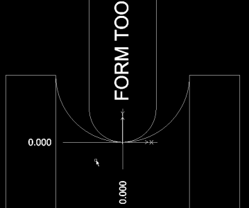
I'm trying to define the X & Y steps that I need to make on my lathe cross slide, to make a 1in diameter cut with a 1/2in diameter form tool.

I accidentally got the X-axis working once, but I've since broken that, and can't get either axis working now. Works pretty slick when it works. You move the form tool around the arc and the X & Y numbers reflect the change from 0,0.

The idea is to move the form tool around the arc in small X & Y increments to achieve a relatively smooth arc with minimal stair stepping. If I can get the CAD tool to work, I would notate the X & Y numbers then "dial it in" on my lathe and DRO.

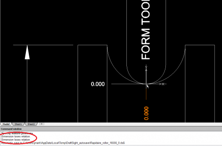
I keep following the prompts but keep getting the "Dimension loses relation" error. I thought perhaps the arcs were confusing the command but I tried the same thing on a sharp corner and got similar non-function.

Can anyone spot what I'm doing wrong?
 

Attachments

  • Roller1.png
    Roller1.png
    11.9 KB · Views: 8
  • Roller1.png
    Roller1.png
    11.9 KB · Views: 7
  • Roller2.png
    Roller2.png
    16.6 KB · Views: 7
Does your DRO have an arc function? I am unfamiliar with the DRO's specifically intended for a lathe but my DRO on the mill has that function. I can specify a tool radius, an arc radius, and the allowable error and it will generate the tool steps. If don't have that function on the lathe but have it on a mill DRO, you could generate the steps and record them.

A couple of decades ago, I needed to cut an Archimedes spiral I was working in AutoCad at the time, very much like Draftsight. Calculated the locus of the curve in Microsoft Excel and generated a and generated a set of straight line motions that followed the curve. I generated G- code based upon those motions.

In your case, you have a .5" radius and a .25" radius on your tool. Depending whether you are cutting an inside or outside curve, the tool path will move on a .25" or .75" radius. The equation for a circle is x^2 + z^2 = R^2 where R is the radius of the tool path and the center of the arc is 0,0. The equation would be rearranged to solve for x; x =sqrt(R^2-z^2). A set of points would be assigned for z and the associated x for each would be calculated. This is your coordinates for the curve.

I can furnish the spreadsheet if you wish.
 
Relate dimension means that when you move your geometry around and don’t move the dimensions with it, the relationship has been lost.

Draftsight used to be a clone of sorts of AutoCAD. Most all of the keyboard controls are identical to version 12 which I learned CAD on in 1996.

Back then you could move the dimensions around without any penalty, they were similar in nature to geometry in how you could manipulate them.

Somewhere along the line, dimensions needed to be associated with geometry, more so than just attaching them to an endpoint or midpoint or center. The driving change behind this was parametric modeling. You can’t have parametric modeling if the dimensions are disassociated from the geometry.

So now, they have to be or you get that type of error. I’m sure there is a setting that can be toggled to turn it off but I’m not sure where that would be.

RJ’s suggestion to do the spreadsheet route is probably the best way to achieve this. Then use the CAD software to input a couple of the coordinates to double check the path and you are good to go.


Sent from my iPhone using Tapatalk
 
I did some modeling in SolidWorks and it appears that if you keep the sum of the x and z step to less than .05", the scallop height should be under .001".
 
RJ, I think I'm picking up what you're laying down. See attached Excel spreadsheet. Is this what you were referring to?

Following VTCNC's suggestion of 0.05in carriage steps it looks like a fairly smooth cut, however there is a discontinuity I haven't figured out at around 0.2 on both sides.

Oops, it won't let me attach an Excel file. Please advise.
If you click on the paper clip at the lower left and select "all supported files" in the lower right, you should be able to attach the file. For my benefit, please save your spreadsheet as the older .xls format rather than the current .xlsx format. It may be that HM doesn't recognize the .xlsx format as well.
 
Here is an Excel spreadsheet that will generate the tool path for cutting an a convex or concave surface on a lathe. It could be polished up a bit. Enhancements would be to calculate the scallop and determine the step size based on that and to set it up to choose the quadrants to cut but the basics are there.
 

Attachments

  • Arc Cut.xls
    21.5 KB · Views: 3
If you click on the paper clip at the lower left and select "all supported files" in the lower right, you should be able to attach the file. For my benefit, please save your spreadsheet as the older .xls format rather than the current .xlsx format. It may be that HM doesn't recognize the .xlsx format as well.

Re-attempt to attach a .XLS spreadsheet. Seems to have worked this time.
 
Back
Top