-
Welcome back Guest! Did you know you can mentor other members here at H-M? If not, please check out our Relaunch of Hobby Machinist Mentoring Program!
You are using an out of date browser. It may not display this or other websites correctly.
You should upgrade or use an alternative browser.
You should upgrade or use an alternative browser.
Edwards Radial 5 build thread --- PHOTOS!
- Thread starter JRaut
- Start date
I know I am posting this way late in the game (tried to find this when I read your tap breaking problem and couldn't remember where I saw it) but you might keep this in mind for future experience. Joe Pieczynski on U-Tube (goes by Joe Pie) has a bunch of helpful machining videos and this one may be of help. He has tons of informative stuff.
I've made a few rings using the Trimble method in the past. But now that I know about the method described in the drawings for the Edwards 5, I'm not sure I'll ever make a ring any other way.
That's what I've read from other Edwards builders so there must be more than one way to skin the cat. The design has a track record of running well so its hard to argue with real life results. I cant wait for yours to pop. You are making fast progress.
- Joined
- Mar 9, 2018
- Messages
- 465
Episode 12A || Pistons and Rings
[Splitting this post up into two because I hit the limit of 30 attachments. This is Part A.]
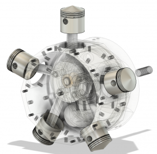
Making the pistons and rings turned out to be a surprisingly easy job, albeit time consuming. The aluminum pistons were straight forward, and a little writeup in the drawings about how to machine the cast iron rings made the job a relative cakewalk.
Pistons
The pistons were all born from a length of 1”-diameter 7075 aluminum. The pistons finish to a bit over 1” in length, so I lopped off five 1-1/2” long sections, giving me plenty of meat to chuck onto. (Actually, I needed 6 sections, as one of them was used to grow my pile of ‘learning opportunities’.)
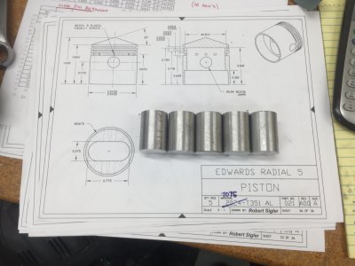
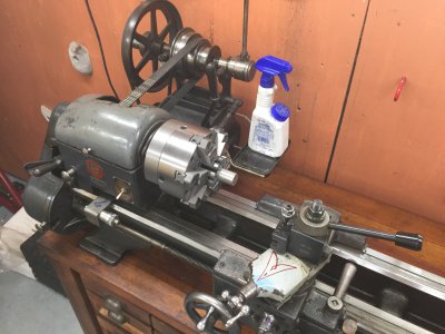
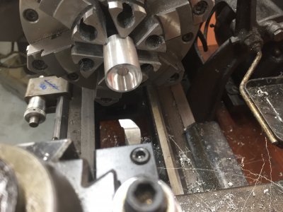
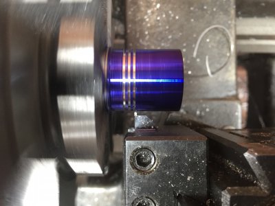
The insides were bored out to finish dimension, then I turned the OD to final dimension and cut in the rings 50-thou deep with a Micro 100 carbide face grooving bar (FG-312-030). Easy peasy.
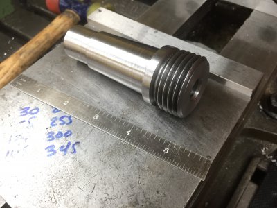
You may recall that I recently acquired a 12” vertical/horizontal rotary table, which has an MT4 center hole. In order to accommodate fast and (reasonably) accurate swapping of lathe work over to the rotary table, I turned up a spindle adapter from some 4140 prehard ---- MT4 on one end, and 1½-8 thread on the other to match my lathe and all of my lathe chucks. The taper isn’t perfect, but it’s pretty good. I reckon I’ll grind it in one day. But not today. I tapped the back end of the MT4 side ½-13 so that I could put in a draw bolt. The chuck threads onto the spindle nose adapter and registers on the face of the rotary table; the draw bolt is there to keep the adapter from being pulled out by threading on the chuck once it seats on the face of the rotab. So, with that adapter made, it’s super quick and super easy to get the piston over to the rotary table without having to spend any effort centering it; and I didn’t have to worry about some silly setup with a million clamps.
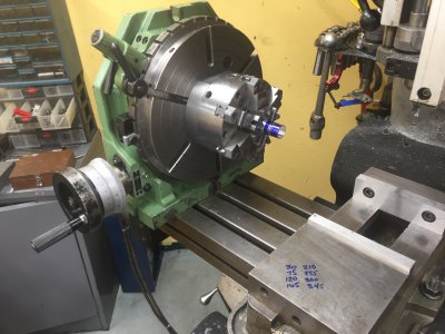
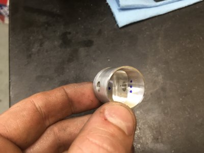
The next features to be machined were the 6mm reamed hole for the wrist pin, and a series of eight 0.043”-diameter holes (#57 drill) equally spaced around the oil ring groove. The rotary table is of course a great tool for such a job. So, with my 6-jaw chuck mounted to the rotary table (without ever unchucking the piston), I indicated along one of the two flats that I had previously milled into the back plate of the chuck, and zeroed the handwheel on the rotary table. This needed to be indicated because the next step in the process involved removing the chuck from the rotary table and grabbing it in my vise using the flats in the back plate. Indicating those flats ensured that I knew where all the cross holes were clocked.
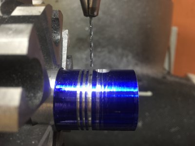
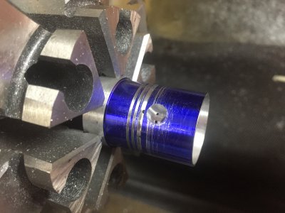
Alright, as I said, the next step was to be done with the chuck in the vise. I (still) kept the piston chucked up, so no worries about losing concentricity. The only indicating necessary was to find the centerline of the part. Easily done with an Indicol. The one feature that I needed to mill in this setup was the pocket to accommodate the small end of the master/link rods. It needs to be milled perpendicular to the reamed 6mm wrist pin hole, which is why I needed to indicate things in when the chuck was mounted to the rotary table.
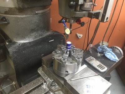
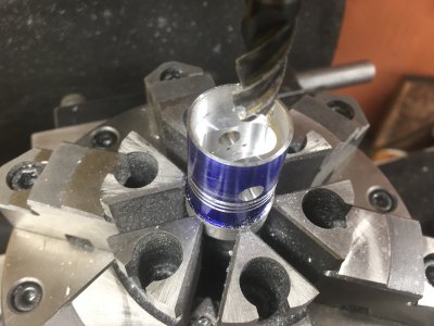
Okay, finally time to remove the piston from the chuck. Off the chuck, I brought it over to the surface plate to scribe the spring line for the piston crown, 860 thou from the base of the skirt.
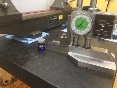
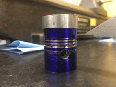
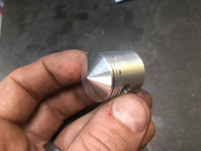
Now I carefully chucked it back up in my 6-jaw. Just tight enough so that it wouldn’t slip while machining, but just loose enough so that it wouldn’t mar the finished OD of the piston. It probably would have been a good idea to machine a slit sleeve clamp, but this worked fine. I’d probably make something like that had I been building a radial with more than 5 cylinders. Once chucked up in the lathe, I finished off the crown of the piston using my compound set at 20 degrees. I didn’t indicate the angle or anything like that, so it’s within a degree or two at best.
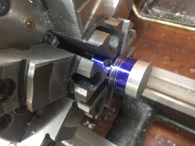
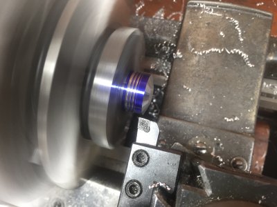
Okay, pistons are basically done! Really, really nice looking parts if I do say so myself. Just need to do a little bit of deburring, and potentially ream out the wrist pin hole a bit using the technique I mentioned in an earlier post.
[Continued in Part B...]
[Splitting this post up into two because I hit the limit of 30 attachments. This is Part A.]
Making the pistons and rings turned out to be a surprisingly easy job, albeit time consuming. The aluminum pistons were straight forward, and a little writeup in the drawings about how to machine the cast iron rings made the job a relative cakewalk.


Pistons
The pistons were all born from a length of 1”-diameter 7075 aluminum. The pistons finish to a bit over 1” in length, so I lopped off five 1-1/2” long sections, giving me plenty of meat to chuck onto. (Actually, I needed 6 sections, as one of them was used to grow my pile of ‘learning opportunities’.)


The insides were bored out to finish dimension, then I turned the OD to final dimension and cut in the rings 50-thou deep with a Micro 100 carbide face grooving bar (FG-312-030). Easy peasy.


You may recall that I recently acquired a 12” vertical/horizontal rotary table, which has an MT4 center hole. In order to accommodate fast and (reasonably) accurate swapping of lathe work over to the rotary table, I turned up a spindle adapter from some 4140 prehard ---- MT4 on one end, and 1½-8 thread on the other to match my lathe and all of my lathe chucks. The taper isn’t perfect, but it’s pretty good. I reckon I’ll grind it in one day. But not today. I tapped the back end of the MT4 side ½-13 so that I could put in a draw bolt. The chuck threads onto the spindle nose adapter and registers on the face of the rotary table; the draw bolt is there to keep the adapter from being pulled out by threading on the chuck once it seats on the face of the rotab. So, with that adapter made, it’s super quick and super easy to get the piston over to the rotary table without having to spend any effort centering it; and I didn’t have to worry about some silly setup with a million clamps.


The next features to be machined were the 6mm reamed hole for the wrist pin, and a series of eight 0.043”-diameter holes (#57 drill) equally spaced around the oil ring groove. The rotary table is of course a great tool for such a job. So, with my 6-jaw chuck mounted to the rotary table (without ever unchucking the piston), I indicated along one of the two flats that I had previously milled into the back plate of the chuck, and zeroed the handwheel on the rotary table. This needed to be indicated because the next step in the process involved removing the chuck from the rotary table and grabbing it in my vise using the flats in the back plate. Indicating those flats ensured that I knew where all the cross holes were clocked.


Alright, as I said, the next step was to be done with the chuck in the vise. I (still) kept the piston chucked up, so no worries about losing concentricity. The only indicating necessary was to find the centerline of the part. Easily done with an Indicol. The one feature that I needed to mill in this setup was the pocket to accommodate the small end of the master/link rods. It needs to be milled perpendicular to the reamed 6mm wrist pin hole, which is why I needed to indicate things in when the chuck was mounted to the rotary table.


Okay, finally time to remove the piston from the chuck. Off the chuck, I brought it over to the surface plate to scribe the spring line for the piston crown, 860 thou from the base of the skirt.


Now I carefully chucked it back up in my 6-jaw. Just tight enough so that it wouldn’t slip while machining, but just loose enough so that it wouldn’t mar the finished OD of the piston. It probably would have been a good idea to machine a slit sleeve clamp, but this worked fine. I’d probably make something like that had I been building a radial with more than 5 cylinders. Once chucked up in the lathe, I finished off the crown of the piston using my compound set at 20 degrees. I didn’t indicate the angle or anything like that, so it’s within a degree or two at best.


Okay, pistons are basically done! Really, really nice looking parts if I do say so myself. Just need to do a little bit of deburring, and potentially ream out the wrist pin hole a bit using the technique I mentioned in an earlier post.


[Continued in Part B...]
- Joined
- Mar 9, 2018
- Messages
- 465
Episode 12B || Pistons and Rings
[Continued from Part A…]
Piston Rings
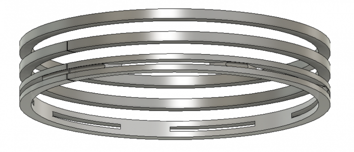
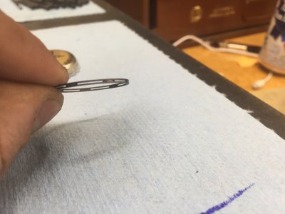
Each piston uses three rings: the upper two are compression rings and the lower is an oil ring. The compression rings are solid, whereas the oil rings have some through-slots and grooves to help distribute oil to the cylinder walls.
The initial machining operations for both types of rings is identical. As has been touched on in several earlier posts in this thread, the method of ring construction described in the drawings is pretty darn ingenious. It doesn’t require any guess and check, or calculations, or heat setting. And the result is a well-sprung piston ring that is perfectly round when it’s fully compressed in the cylinder bore. It goes something like this:
(1) Chop off a chunk of cast iron about 3 inches long. I had some 1-1/4” diameter rod, so that’s what I used.
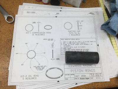
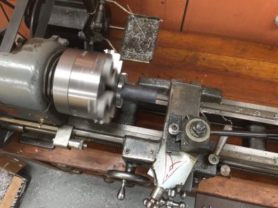
(2) Chuck it up at the lathe and rough bore to about 7/8” ID and rough turn the OD to about 1”.
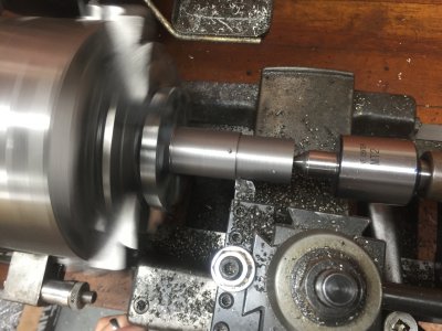
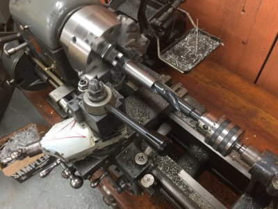
(3) Bring it over to the mill and mill a full-length slot 0.080” wide. This width will be the amount of spring present in the ring after you’re done making it. (I should have put a chock in the other side of the vise. But I didn’t. Sue me.)
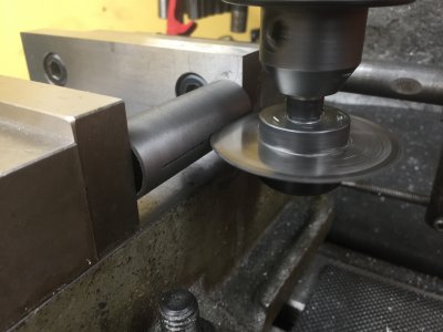
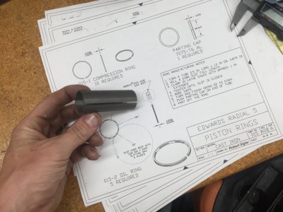
(4) Bring it back to the lathe. Chuck it up TIGHT so that the 0.080” gap closes all the way. Any more stickout than about 1” and the gap won’t close all the way.
(5) Finish bore the ID to 0.875” and finish turn the OD to 0.944”, which is the same as the cylinder bore, maybe a thou less.
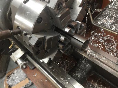
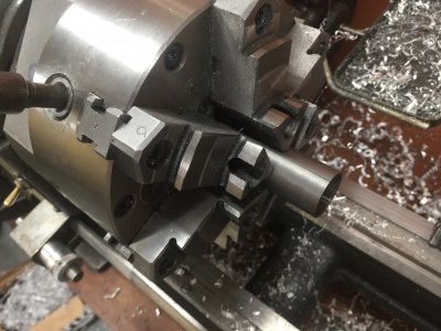
After this step, construction of the compression vs. oil rings differs. The compression rings are easy, just:
(6) Slip a ‘parting cap’ over the end of the tube and part off a ring to the appropriate length. See my discussion of my epic fail a few posts earlier to see just how important that parting cap really is.
(7) Repeat step 6 until you’ve got enough rings, plus a few extra.
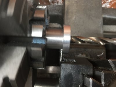
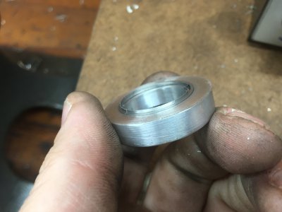
After parting off, I was left with a burr all the way around the ring. I used the sharp corner of a V-block to knock it off. Then a few swipes on some 220 grit sandpaper, both sides. Viola!
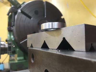
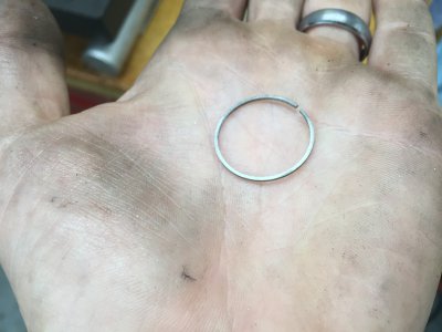
Construction of the oil rings was more complex. I left the finish turned and bored cast iron tube in the lathe chuck and brought it over to my 12” rotary table on the Bridgeport, lying flat. I chucked up a 0.015”-thick slitting saw in my new-to-me quick-change setup (!!!!!). Construction basically went as follows:
(6) Center everything up, and note the angle on the rotary table where the ring gap is located.
(7) Slit off a very thin slice of the tube right at the top to make sure everything is flat and to set a Z=0 location.
(8) Move the quill down such that the slitting saw is centered on the ring thickness. Cut a 0.010”-deep slot around the full perimeter of the ring.
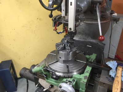
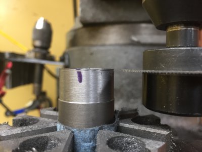
(9) At the 6 locations specified on the print, plunge 0.065” into the ring to get the through-thickness slots.
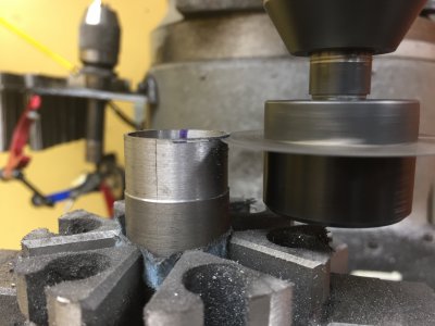
(10) Move the quill down to the bottom of the ring. Install the ‘parting cap’ and part the ring off.
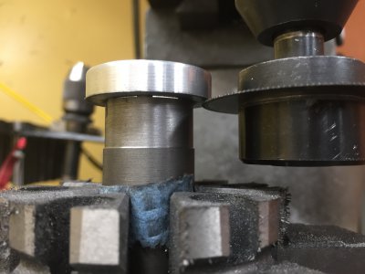
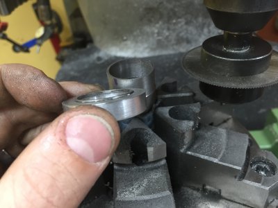
A few swipes on some sand paper and she’s good to go! An insanely delicate looking part, but quite frankly, not all that difficult to machine if you’ve got the right tools and cutters.
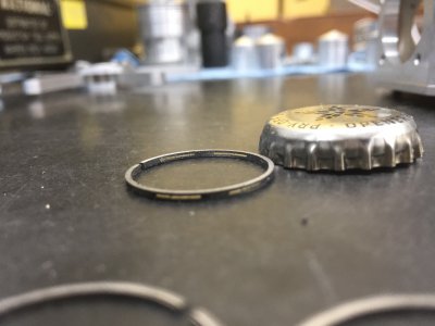
All the rings and all the pistons still need a little bit of debur and some fine adjustments to make sure everything fits, but I’ll save all that for closer to final assembly. (Not pictured are a bunch of extra rings, both types. Just in case.)
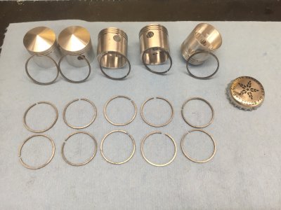
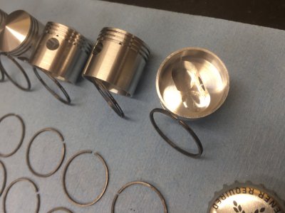
Anyway, some really nice looking parts in this post! Sure is coming along now.
Next up: CLEAN EVERYTHING! There’s cast iron dust all over my shop, on all my ways, and in all my chucks.
TIME ON PISTONS AND RINGS: 22 hours
CUMULATIVE TIME: 212 hours
[Continued from Part A…]
Piston Rings
Each piston uses three rings: the upper two are compression rings and the lower is an oil ring. The compression rings are solid, whereas the oil rings have some through-slots and grooves to help distribute oil to the cylinder walls.
The initial machining operations for both types of rings is identical. As has been touched on in several earlier posts in this thread, the method of ring construction described in the drawings is pretty darn ingenious. It doesn’t require any guess and check, or calculations, or heat setting. And the result is a well-sprung piston ring that is perfectly round when it’s fully compressed in the cylinder bore. It goes something like this:
(1) Chop off a chunk of cast iron about 3 inches long. I had some 1-1/4” diameter rod, so that’s what I used.


(2) Chuck it up at the lathe and rough bore to about 7/8” ID and rough turn the OD to about 1”.


(3) Bring it over to the mill and mill a full-length slot 0.080” wide. This width will be the amount of spring present in the ring after you’re done making it. (I should have put a chock in the other side of the vise. But I didn’t. Sue me.)


(4) Bring it back to the lathe. Chuck it up TIGHT so that the 0.080” gap closes all the way. Any more stickout than about 1” and the gap won’t close all the way.
(5) Finish bore the ID to 0.875” and finish turn the OD to 0.944”, which is the same as the cylinder bore, maybe a thou less.


After this step, construction of the compression vs. oil rings differs. The compression rings are easy, just:
(6) Slip a ‘parting cap’ over the end of the tube and part off a ring to the appropriate length. See my discussion of my epic fail a few posts earlier to see just how important that parting cap really is.
(7) Repeat step 6 until you’ve got enough rings, plus a few extra.


After parting off, I was left with a burr all the way around the ring. I used the sharp corner of a V-block to knock it off. Then a few swipes on some 220 grit sandpaper, both sides. Viola!


Construction of the oil rings was more complex. I left the finish turned and bored cast iron tube in the lathe chuck and brought it over to my 12” rotary table on the Bridgeport, lying flat. I chucked up a 0.015”-thick slitting saw in my new-to-me quick-change setup (!!!!!). Construction basically went as follows:
(6) Center everything up, and note the angle on the rotary table where the ring gap is located.
(7) Slit off a very thin slice of the tube right at the top to make sure everything is flat and to set a Z=0 location.
(8) Move the quill down such that the slitting saw is centered on the ring thickness. Cut a 0.010”-deep slot around the full perimeter of the ring.


(9) At the 6 locations specified on the print, plunge 0.065” into the ring to get the through-thickness slots.

(10) Move the quill down to the bottom of the ring. Install the ‘parting cap’ and part the ring off.


A few swipes on some sand paper and she’s good to go! An insanely delicate looking part, but quite frankly, not all that difficult to machine if you’ve got the right tools and cutters.


All the rings and all the pistons still need a little bit of debur and some fine adjustments to make sure everything fits, but I’ll save all that for closer to final assembly. (Not pictured are a bunch of extra rings, both types. Just in case.)


Anyway, some really nice looking parts in this post! Sure is coming along now.
Next up: CLEAN EVERYTHING! There’s cast iron dust all over my shop, on all my ways, and in all my chucks.
TIME ON PISTONS AND RINGS: 22 hours
CUMULATIVE TIME: 212 hours
Last edited:
- Joined
- Mar 9, 2018
- Messages
- 465
Episode 13 || Cylinder Liners
This ought to be a pretty quick post.
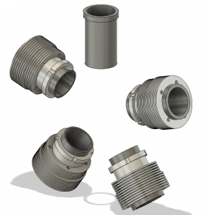
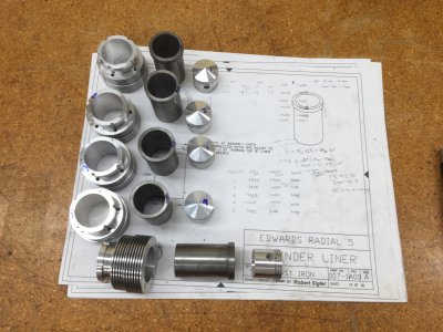
I had just finished machining all the cast iron rings and had a massive mess of CI dust all over my shop and in my 6-jaw chuck. Rather than spending a bunch of time taking all that stuff apart and cleaning it up, I figured I’d get the rest of the CI work out of the way first. The only other CI components on this motor are the cylinder liners --- just glorified tubes of cast iron. Easy.
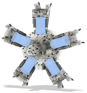
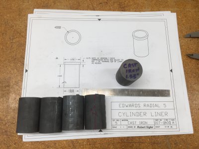
As always, I started over at my little 4x6 bandsaw. Chopped up five chunks of cast iron, each 2 inches long. Later I chopped up another because I felt like adding a part to my scrap heap --- accidentally over-bored it by about 4 thou; may have been just fine, but I had enough material to do it right. Anyway, I chucked each chunk up in the lathe, faced it off, drilled a 1/2” through-hole, and put in a center.
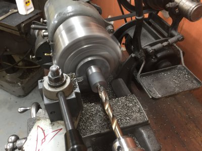
With a live center in place, I rough-, then finish-turned the OD to final dimension. Each OD was customized to achieve a 1-thou interference fit with the cylinder barrel it’d mate with.
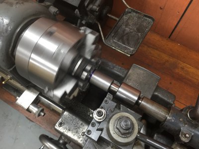
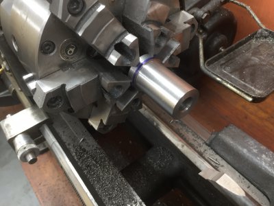
I flipped the part around in the chuck and enlarged the through-hole. First with a S&D drill, then with a boring bar. Similar to the OD, each ID was customized such that it’d be 1.5-thou larger in diameter than the piston it’d mate with. The drawings call for a gap of between 1.5 and 2.5 thou; I went for the tight end of that in case I want to lap or hone the bores. They came out remarkably smooth and virtually taper free, so I’ll probably just leave them as is, save for a quick hone to get some cross-hatching.
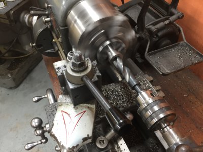
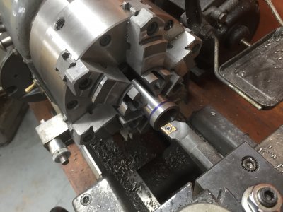
The cylinder heads will eventually sit on top of the liner flange. Thicker flange means less compression, thinner flange means higher compression. The drawings call for fine tuning the flange thickness during final assembly to achieve a compression ratio of 8.5:1. So later on I’ll have to chuck each assembly on an expanding arbor to do the final operation. But that’ll be much later. So I finished off the flanges with a bit of extra meat on them for now. All done. Easy peasy.
Lots of CI chips and dust though! Now I’m going to have to really clean everything up before moving on to the next components.
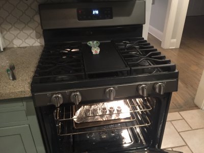
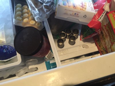
Last step in the process here is to mate the liners with the cylinder barrels. There’s a nominal interference fit of 1 thou between the two. So I waited until my wife went to bed, then snuck up to the kitchen. I tossed the aluminum barrels in the oven at 375F and the cast iron sleeves in the freezer and let’em both sit there for about 20 minutes. Running through the thermal calculations made that 1-thou interference fit turn into a 3-thou clearance. As expected, everything dropped right in. My arbor press was on standby but wasn’t required.
Lookin’ good!
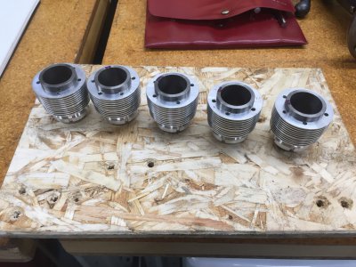
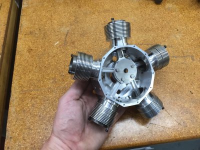
All in all, they took a bit longer than I expected for such a simple part. But making sure I had both the ID and OD on size was pretty finicky. Each ID and each OD of each of the five liners is within a few tenths of my target dimension.
TIME ON CYLINDER LINERS: 8 hours
CUMULATIVE TIME: 221 hours
This ought to be a pretty quick post.
I had just finished machining all the cast iron rings and had a massive mess of CI dust all over my shop and in my 6-jaw chuck. Rather than spending a bunch of time taking all that stuff apart and cleaning it up, I figured I’d get the rest of the CI work out of the way first. The only other CI components on this motor are the cylinder liners --- just glorified tubes of cast iron. Easy.


As always, I started over at my little 4x6 bandsaw. Chopped up five chunks of cast iron, each 2 inches long. Later I chopped up another because I felt like adding a part to my scrap heap --- accidentally over-bored it by about 4 thou; may have been just fine, but I had enough material to do it right. Anyway, I chucked each chunk up in the lathe, faced it off, drilled a 1/2” through-hole, and put in a center.


With a live center in place, I rough-, then finish-turned the OD to final dimension. Each OD was customized to achieve a 1-thou interference fit with the cylinder barrel it’d mate with.


I flipped the part around in the chuck and enlarged the through-hole. First with a S&D drill, then with a boring bar. Similar to the OD, each ID was customized such that it’d be 1.5-thou larger in diameter than the piston it’d mate with. The drawings call for a gap of between 1.5 and 2.5 thou; I went for the tight end of that in case I want to lap or hone the bores. They came out remarkably smooth and virtually taper free, so I’ll probably just leave them as is, save for a quick hone to get some cross-hatching.


The cylinder heads will eventually sit on top of the liner flange. Thicker flange means less compression, thinner flange means higher compression. The drawings call for fine tuning the flange thickness during final assembly to achieve a compression ratio of 8.5:1. So later on I’ll have to chuck each assembly on an expanding arbor to do the final operation. But that’ll be much later. So I finished off the flanges with a bit of extra meat on them for now. All done. Easy peasy.
Lots of CI chips and dust though! Now I’m going to have to really clean everything up before moving on to the next components.


Last step in the process here is to mate the liners with the cylinder barrels. There’s a nominal interference fit of 1 thou between the two. So I waited until my wife went to bed, then snuck up to the kitchen. I tossed the aluminum barrels in the oven at 375F and the cast iron sleeves in the freezer and let’em both sit there for about 20 minutes. Running through the thermal calculations made that 1-thou interference fit turn into a 3-thou clearance. As expected, everything dropped right in. My arbor press was on standby but wasn’t required.


Lookin’ good!


All in all, they took a bit longer than I expected for such a simple part. But making sure I had both the ID and OD on size was pretty finicky. Each ID and each OD of each of the five liners is within a few tenths of my target dimension.
TIME ON CYLINDER LINERS: 8 hours
CUMULATIVE TIME: 221 hours
Last edited:
I agree that is going to be one beautiful engine when you are done. If I would have put those parts in my wifes oven I would have been a DEAD man. My wife can smell 1 part per trillion of solvents or cutting oil.
Roger L
Roger L
Last edited:

