Episode 14 || Cam Ring Assembly
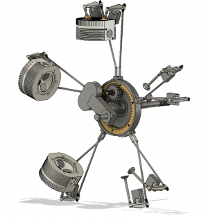
Alright folks. Long time coming on this one. Trying to re-paint the exterior of my house before the snow comes, so not as much shop time as I’d like. The main topic of this post will be the cam ring with four cam lobes and design changes to it, but I’m also tossing in here some smaller associated components as well.
This assembly is geared to the crankshaft and actuates the intake and exhaust valves.
 Change in Design
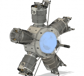
I’ll start with what I changed about the design. Here are a couple side-by-side shots from Fusion showing the as-specified (left) and as-modified/built (right). This primary change is driven entirely by the need (or perceived need, at least) to be able to fine tune the valve timing. As
@petertha pointed out in an earlier post on this thread and
discussed at length here, the gear train as-designed does not really allow for exact setting of the valve timing. Not easily or conveniently, at least. I had been planning this change since I first looked at the drawings, but the discussion over at the link above really solidified the decision for me.
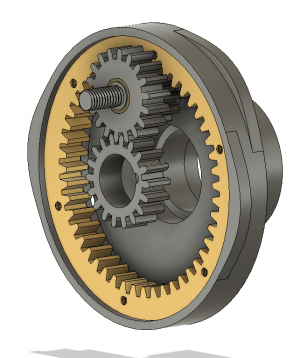
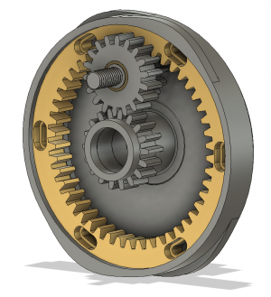
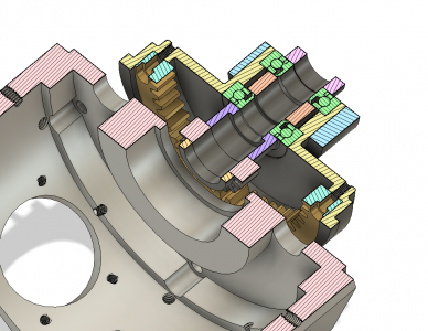
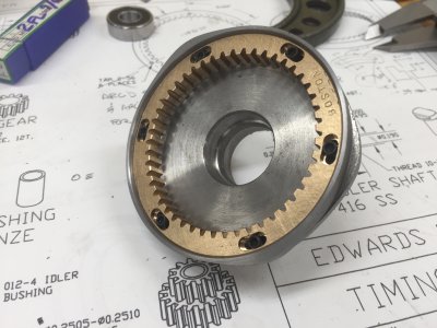
The basic gist of the modification is to allow for the internal cam gear to be rotated with respect to the cam ring (and cam lobes) by up to one tooth space, or 7.5 degrees for this 48-tooth gear. In my modified version, I used 8 degrees to make the numbers a little cleaner. With this added adjustability, the engine is assembled with the valve timing close (i.e., within 1 tooth space), then can be fine-tuned later on. As you can see from the images above, I accomplished that by using slotted arcs to accommodate the #2 socket head cap screws. I also flipped the screw direction, so the arc slots are two-tiered to accommodate the head of the screw.
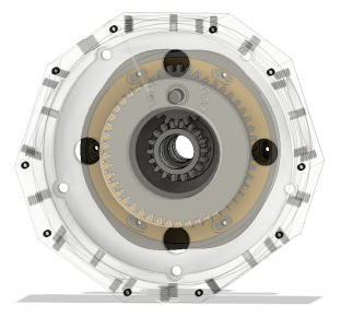
The other modification related to this is that I ‘clocked’ the position of the 6 #2 screws---which connect the internal cam gear to the cam ring---by 30 degrees. Clocking these makes it so that, with the #1 piston at TCD, I can access a couple of the screws through the oil vents in the main crankcase to adjust and then lock down the timing via cam gear rotations. A bit hard to tell from the screenshot below, but you can see two of the screw holes through the left and right vents in the crankcase. The image on the right is a plan section right through those crankcase vents, which align with the #2 screws in the ring gear when the #1 piston is at TDC.
The above probably isn’t really of interest to 99% of you. But the hope is that, should anyone reference this post when building one of these engines in the future, they’ll be able to glean some good insight from it.
Okay, that was a lot of theory. Let’s get into the machining.
Cam Ring
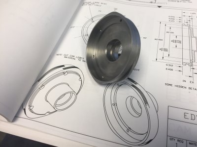
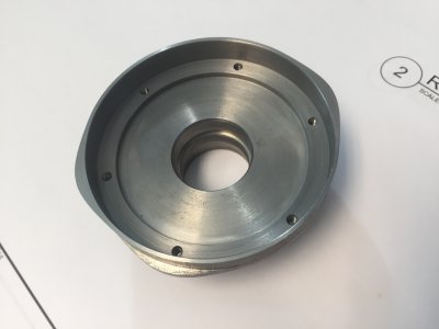
This was no-doubt the most complex component in this assembly. It’s got two precision bores for bearings, 4 cam lobes, and a bunch of other features as well. And I machined it out of 4140 Prehard, which is a darn tough bit of steel. I started with a nice 3”-diameter chunk of it. I first roughed everything I whittled down the bearing side to final dimension the reversed it in my 6-jaw chuck.
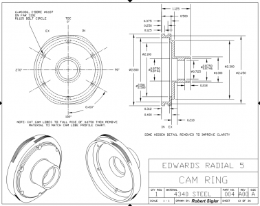
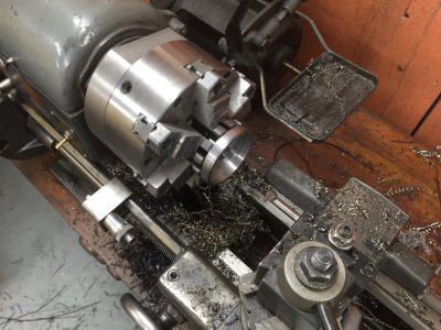
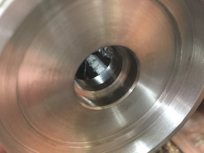
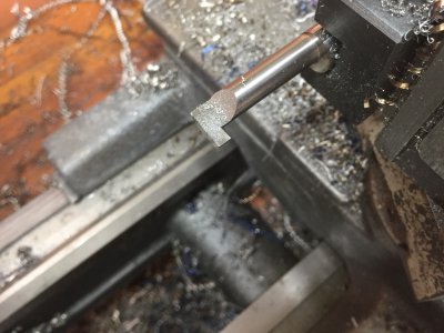
The only magic in the turning operation of the cam ring was this: the cam ring runs on two bearings, which are separated by a step. Not sure if that makes much sense, but look at the drawing to see what I’m talking about. In order to get these two bearing races dead concentric, I turned them in one setup. It was pretty tricky because of the step. I purchased a Micro 100 internal grooving bar so that I could back-turn the shoulder for the ‘rear’ bearing. If that makes sense…. These are tight-tolerance bores, so it was pretty finicky getting them right, but the dead-sharp Micro 100 boring bar helped matters, as I could take some whisper cuts if needed.
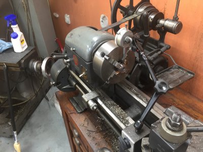
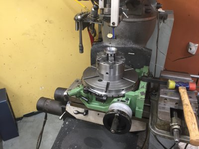
Alright, with all the turning complete, I moved the cam ring over to my rotary table, still mounted in my 6-jaw chuck. The arbor I made for mounting my chuck to my rotary table is a hair out, so I trued everything up with the adjust-tru feature on my chuck. Wicked awesome. After centering it up, I machined out the groove between the intake and exhaust lobes using a 1/8”-wide woodruff cutter. Easy peasy.
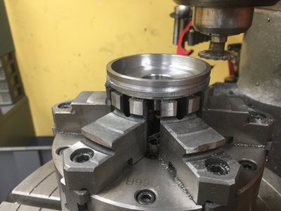
Alright, now we get to the tricky bits: the cam lobes.
NOTE: The way I cut these cam lobes is, strictly speaking, WRONG. The profile I ended up with is slightly different from the profile called out in the drawings. My cams are a bit gentler and have about 7% less total ‘cam area’ than is shown in the drawings. I don’t know if this’ll actually matter in the final engine, but I doubt it will, so I went with it.
The drawings very clearly---in tabular format---spell out the amount of cam lift for every one degree of rotation. So all I did was, with a woodruff cutter in the spindle, follow the recipe prescribed in the drawings: I sequentially turned my rotary table 1 degree, then fed in on my mill’s Y-axis until I cut away the right amount of material. The turned another 1 degree and repeated. I just repeated this for each degree of each of the cams until I made it all the way around. It was actually not all that difficult, just time consuming and took a good bit of concentration. Before I run it, I need to smooth things out a bit, because the net result is cams that have a slight stairstep to them.
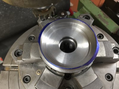
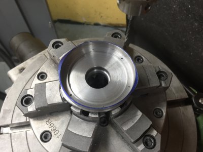
After drilling and tapping for 6 #2 screws for the ring gear, I was finished.
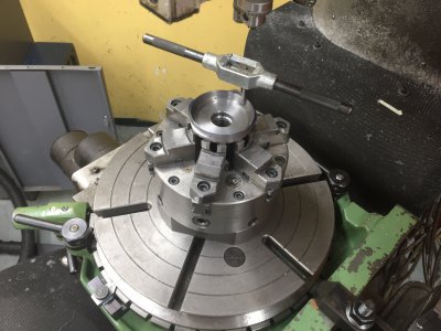
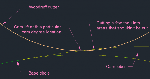
So why are these cam lobes wrong, you ask? Well, it’s because the cams have a quicker ‘rise’ in them than the woodruff cutter can accommodate. So for example, if I was working on taking off material for the cam at the 320-degree position, it was
also taking off material associated with the 321-degree position that should not have been taken off. It’s difficult to put into words, so here's a diagram. A RIGHT(er) way to have done this would be to, at each degree mark around a given cam lobe, infeed the cutter until any part of the cutter makes contact with any part of the cam lobe. The maximum amount of excess cutting I saw was a few thousandths, which I reckoned would be acceptable.
Anyway, I think that discussion too will be of little/no interest to 99% of readers.
Cam Ring Gear
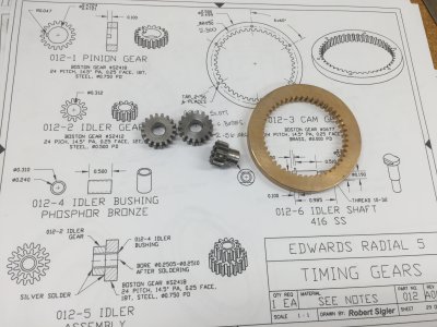
The cam ring gear, surprise surprise, sits inside the cam ring. It starts as an off-the-shelf brass gear from Boston Gear (#G677). I thought about trying to make this, and the other gears in the build. But then I decided against it. One of the next projects in my long, long list will have a bunch of gears which I’ll cut myself. Anyway, I made an arbor out of some scrap aluminum to hold the gear, then turning down the OD so it’d be a nice, sliding fit inside the recently-machined cam ring.
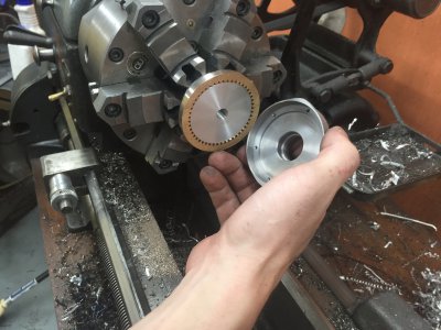
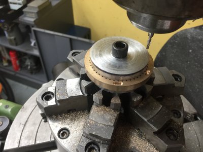
Then I shifted everything over to the rotary table to tackle the 8-degree arc slots to accommodate the #2 socket head cap screws. I milled the through-slots with a 0.090”-diameter end mill (4 thou clearance) and I milled the slots for the heads with a 9/64” end mill (nominally on size, but probably a couple thou clearance). I purposefully left very, very little clearance, as I was taking a good amount of meat out of the ring gear already. All said and done, everything fit
perfectly! The ring slides super smoothly along its full 8-degree range of motion and locks down easily with the #2 screws snugged down.
 Oil Pump Cam
I
already posted the
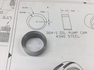
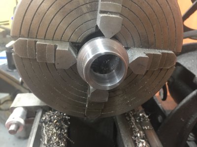
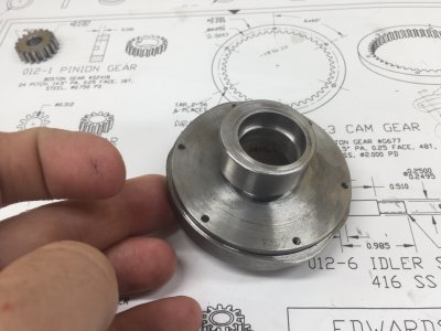
wrong way to machine the oil pump cam. Here it is correctly machined, polished up, and pressed into its final location on the cam ring. It’s about a 2 thou interference fit.
 Idler Shaft
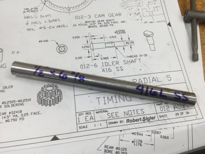
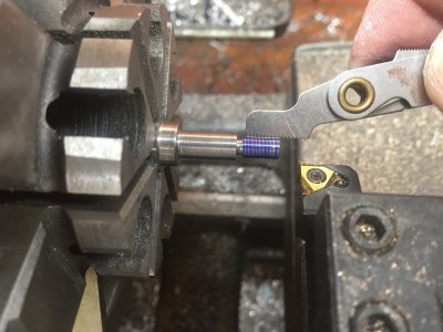
This shaft, machined from 416 Stainless, screws into the crankcase and carries a gearset. It was pretty straightforward, so I won’t dwell on it. Only thing I’ll say is that I was getting a pretty poor surface finish, regardless of speeds/feeds, so I just polished all the final diameters using a fine-cut file followed with some emery cloth. Oh, one more thing: the drawings call out the head to be 0.100” thick. That results in an interference with the cam ring. I machined my to 0.080” and it fits great.
 Other Gears and Gearset
I’m running out of steam typing all this up, so I won’t spend much time on this either. Also, it was all pretty straightforward, as I started with off-the-shelf gears from Boston gear. Funny enough, these gears were all available from Amazon, which also happened to have the lowest prices. So that’s where I got them all from (including the internal ring gear discussed earlier).
One of the gears needed its ID bored/reamed to 12mm, then a 3/32” key slot milled into it. I opened up the bore on the lathe using a piece of aluminum scrap that I turned into a slit clamp. Machined it to just fit the gear, slipped in the gear, then tightened the chuck down a bit more to get a dead firm grip. Easy.
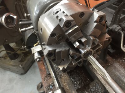
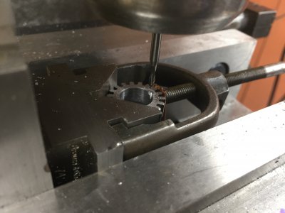
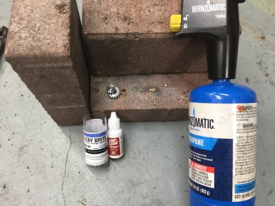
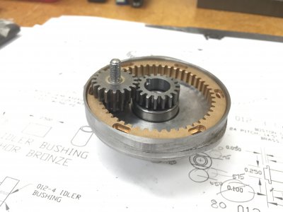
The last thing to be done was make up a gearset comprising a small 12-tooth gear and a larger 18-tooth gear silver soldered onto a bronze bushing. I discussed my foray into silver soldering a little bit
in this other thread. Up until this project, I had always just thought the term “silver solder” was a less-than-technically-sound description for silver brazing. So I went down the silver brazing rabbit hole before realizing that silver-bearing solder (~4% silver or so) actually exists, and is much easier than silver brazing. Anyway, after boring out the stock gears and turning the bronze bushing, I just silver
soldered the gearset together with no complications whatsoever. Easy peasy. Last step was to bore out the ID of the assembly for a free running fit on the SS idler shaft. I did that ‘off camera’ using the same slit aluminum clamp strategy to grab onto the assembly.
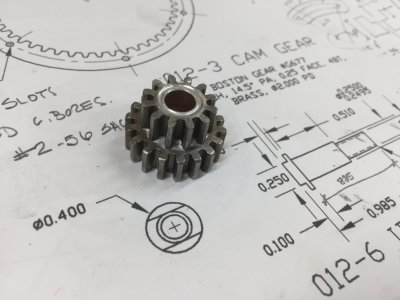
And here it is all together! There are a bunch of spacers associated with this part that I haven’t yet made (and probably won’t show in future posts, as they’re just spacers). And I haven’t yet pressed in the bearings into the cam ring, as I’m not sure I’ll ever be able to get them out once I press them in.
Not sure what the next component will be, maybe the cylinder heads. What I am sure of, though, is that it’ll probably be a good long while before I post a new episode. Most of the parts that remain will take a good deal of finicking and fixturing, which all takes time.
TIME ON CAM RING ASSEMBLY: 28 hours
CUMULATIVE TIME: 250 hours
Edit 9/16: The gearset is made up from 12 and 18T gears, not 12 and 24.
