Edwards Radial 5 build thread --- PHOTOS!

Hey @petertha, I'm just seeing your post now. Thanks for the info, looks like a real treasure-trove! I always get nervous websites like that will just one day disappear and we'll lose all that good information to time.

A lot less In/Ex overlap on the Edwards than all the O/S motors, huh? That's a bit surprising.

Tackling which carb to get and how to jet it is still on my to-do list. The carb recommended in the Edwards drawings is a Perry #302 or Perry #205. Neither of those are made any more (or perhaps the model numbers just changed), but Perry is still a business. I intend to give them a call once I get closer to completion.
 
Episode 15 || Rocker Arms

Well it’s hard to believe that I haven’t made any progress on my Edwards in a year. Time flies when you have two small children, a full time job, and are dealing with an ongoing worldwide pandemic. I guess I’ll forgive myself. I’m excited to get back into the swing of things.

I started making these rocker arms over a year ago and just recently finished them off, so the early stages of making them are a bit blurry. They’re shown in the drawings with fairly complex geometry, but that’s mostly just for the look. None of the dimensions are all that important, which is good, because I wasn’t all that accurate in making them.

Fusion_01.PNG Fusion_02.PNG

Steps 1/2 -- I used a regular hacksaw to cut out 12 blanks from a plate of 7075-T6 aluminum. Only 10 are needed for the engine, but ya know… screw-ups and such. Then I squared them all up on the Bridgeport to the overall dimensions.
IMG_7970.JPG IMG_7971.JPG

Steps 3/4 -- I clamped each part sequentially in the vise and milled out the overall profile using the modest 2-axis CNC capabilities on my Bridgeport. Mostly I used the CNC to get the radii put in without having to deal with a rotary table. These are all non-critical features, so I could have done it all with a file and been fine. Then I drilled/reamed and drilled/tapped the two ‘vertical’ holes in the same setup.
IMG_7974.JPG IMG_7976.JPG

Steps 5/6 -- I made up a little fixture plate from some scrap aluminum to machine out the next features. It has a dowel pin hole corresponding to the reamed hole from Step 4. I used this fixture to drill/ream the rocker pivot holes.
IMG_7982.JPG IMG_7984.JPG

Steps 7/8 -- 
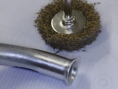
Fast forward an entire year. I used the same fixture block to carve out the bottom side of the rocker arms. They were again located in the fixture block with a dowel pin, and were secured with a 4-40 screw through the rocker pivot hole. Last step was to modify the fixture a little and machine the tapered part on the top of the rocker arm.
IMG_1009.JPG IMG_1020.JPG

They’ll need a lot of cleanup/debur/etc., but they look great! Here are half ready for the last step, and half fully complete. Bottle cap for scale. Again, only 10 are needed, but all 12 made the journey from raw stock. I’ll pick the two worst ones and keep them as spares.
IMG_1021.JPG

The next major component will be the heads. They’re the most complex part of the build and I’m looking forward to getting right back into the swing of things.


TIME ON ROCKER ARMS: 14 hours [split about 50/50 in 9/2020 and 9/2021]
CUMULATIVE TIME: 265 hours
 
Tackling which carb to get and how to jet it is still on my to-do list. The carb recommended in the Edwards drawings is a Perry #302 or Perry #205. Neither of those are made any more (or perhaps the model numbers just changed), but Perry is still a business. I intend to give them a call once I get closer to completion.
I went through a similar exercise for my 50cc 5-cylinder radial this summer. The plans specified a 2 stroke glow (Magnum XL-15A). I think Magnum was a clone of an OS but anyways its ancient history now, no longer produced. And actually what I came to realize is that glow engine selection is shrinking dramatically. The sport is giving way to electrics or maybe like may things, change & extinction happens. Also you may find a manufacturer uses the same carb for a .25 & .35 or .25 and .15

To complicate matters I discovered I actually bought the wrong equivalent to this carb, years go now. I of all people should know better because I used to race 'club 20' (~ 0.21 CI engines) to keep the pylon racing thumbs busy over winter. Orifice sizes can vary dramatically on engines of similar displacement depending on many variables. Could be anything from 4-7mm depending on race/sport/boat engine, how much (if any) needle valve assembly occurs through the throat, engine timing, tuned pipe, pressurized fuel.... etc.

The other issue was I finished machining my intake manifold and it had the counterbore size specific to the carb body. That really painted me into a corner because carb body diameters vary all over the map. I didn't want to get into sleeving & potential seal issues. I also didn't like how my induction tubes were coming into the manifold so long story short, I took step backwards, redesigned the entire manifold & induction tubes AND modified it so I could slap on different carbs trial & error mode with a common adapter plate. I ended up ordering an OS carb & 2 Perry carbs. Just finished the adapter plates the other day. You are correct, Perry is still alive. It was purchased by Conley who needs no introduction to his prior business with model V8's & such. http://www.perrypumps.com/prod01.htm

But getting back to sizes, I went to that same Sceptre site I was mentioning & did a tabulation of methanol 4S engines. Some of the engine review articles measured the carb sizes. My simple logic was if it worked for those engines it should work for mine. However there is proabbly more to it than that. Carbs are feeding multi-cylinders at a slightly higher net rate but I have no calculation method to support how much to factor that. Anyways, here are my plots for your viewing pleasure.
 

Attachments

  • SNAG-2021-09-18 8.59.29 AM.jpg
    SNAG-2021-09-18 8.59.29 AM.jpg
    33.9 KB · Views: 6
  • SNAG-2021-09-18 8.59.14 AM.jpg
    SNAG-2021-09-18 8.59.14 AM.jpg
    217.7 KB · Views: 7
Last edited:
Here is a snip I saved from fellow on HMEM that built this (Youtube) Edwards. The HMEM link doesn't work anymore but this is the info

Hi Edwards Radial enthusiasts. I finished building my engine in 2015 and it has been running happily ever since on a Perry 2100 carb. At the time I emailed Gary Conley at Perry carbs. and described the engine and this is the model he recommended for the application. It has a throat dia. of .270". I just looked at their web page and this carby is still listed.


OS, Saito & others also made radials but I had a tough time finding the corresponding carb sizes. Model numbers yes, but orifice diameter no. But I got the impression they were not much different than the single cylinder equivalent. It could be that idling & transition trumped top end rpm. I ordered the top 2 Perry's on that basis but chart shows the post 145 carb by comparison. I have a carb in that size so hopefully I'm covered when it comes time to running. The Perry's are plastic body & a bit rough around the edges compared to modern Japan carbs, but hopefully functionally do the same thing. Also some of the modern 2S carbs have needle valve & & fuel nipple at angles that may or may not play nice with your engine.
 

Attachments

  • SNAG-2021-09-18 9.10.07 AM.jpg
    SNAG-2021-09-18 9.10.07 AM.jpg
    139 KB · Views: 7
  • SNAG-2021-09-18 9.12.55 AM.jpg
    SNAG-2021-09-18 9.12.55 AM.jpg
    40.7 KB · Views: 6
  • SNAG-2021-09-18 9.16.33 AM.jpg
    SNAG-2021-09-18 9.16.33 AM.jpg
    26.2 KB · Views: 13
Not to mess up your Edwards built post with my O5 pics but hopefully this might benefit you. Here is my redesigned manifold work in progress. You can see the bolt-on carb adapter plate vs original design was integrated. I think this is a better way to go in some fashion.

My induction tubes now enter in kind of a pinwheel orientation vs radial spoke. Long story which I wont delve into, but on these pipe installations you typically have to choose 1 of 2 options: a defined tubing path (which means a custom bend radius). Or you start with a defined radius (an existing tube bender tool) and work out a resulting layout. My tubes are actually a straight + curve + straight (essentially a 2D) part so this was the best I could do. If you have a 3D path to bend & a trumpeted end into the head... well, may the Force be with you. LoL
 

Attachments

  • IMG_4086_edited-1.jpg
    IMG_4086_edited-1.jpg
    338.2 KB · Views: 14
  • SNAG-2021-07-31 11.36.31 PM.jpg
    SNAG-2021-07-31 11.36.31 PM.jpg
    118.8 KB · Views: 15
  • IMG_4075_edited-1.jpg
    IMG_4075_edited-1.jpg
    214 KB · Views: 11
  • IMG_4080_edited-1.jpg
    IMG_4080_edited-1.jpg
    260.2 KB · Views: 10
Last edited:
it has been running happily ever since on a Perry 2100 carb
I'd narrowed my carb options down to one of three Perry carbs from their website based primarily on the dimensions provided in the Edwards drawings, of which the 2100 was the top contender. I also made an extensive catalog of engine displacement vs. carb flow area based on the info on the Perry website to make sure I was on the right track. Most/all of the engines on the Perry website are single-cylinder models; my understanding is the same as yours in that, as long as the cylinders are not firing simultaneously, the carb should be sized based on the displacement of one cylinder.

The Edwards drawings seem to call for a carburetor inlet diameter of 0.281 in, which equates to a flow area of 0.062 in2. They also call for a carburetor OD neck clamping diameter of 0.437 inches. That's a non-critical dimension, but it's informative because some of the Perry carbs have that exact carburetor dimension.

1632753915471.png

Carb No.ID of carb [in.]O.D. of carb [in.]Carb flow area / Edwards flow area
Edwards dwgs.0.2810.437[100%]
Perry 10500.2700.47092%
Perry 10510.3150.470123%
Perry 21000.2700.43792%


OS, Saito & others also made radials but I had a tough time finding the corresponding carb sizes. Model numbers yes, but orifice diameter no. But I got the impression they were not much different than the single cylinder equivalent. It could be that idling & transition trumped top end rpm. I ordered the top 2 Perry's on that basis but chart shows the post 145 carb by comparison. I have a carb in that size so hopefully I'm covered when it comes time to running. The Perry's are plastic body & a bit rough around the edges compared to modern Japan carbs, but hopefully functionally do the same thing. Also some of the modern 2S carbs have needle valve & & fuel nipple at angles that may or may not play nice with your engine.
I'm pretty sure I went through the exact same exercise as you, and made the exact same excel sheet.

I do believe I'll be ordering the Perry 2100, but that'll be a little while down the road probably.
 
Last edited:
Not to mess up your Edwards built post with my O5 pics but hopefully this might benefit you. Here is my redesigned manifold work in progress. You can see the bolt-on carb adapter plate vs original design was integrated. I think this is a better way to go in some fashion.

My induction tubes now enter in kind of a pinwheel orientation vs radial spoke. Long story which I wont delve into, but on these pipe installations you typically have to choose 1 of 2 options: a defined tubing path (which means a custom bend radius). Or you start with a defined radius (an existing tube bender tool) and work out a resulting layout. My tubes are actually a straight + curve + straight (essentially a 2D) part so this was the best I could do. If you have a 3D path to bend & a trumpeted end into the head... well, may the Force be with you. LoL
I just ordered a tube bending kit from Hemingway Kits.

Bending up the in/ex pipes will still be down the road a bit, and I'm sure making the Hemingway kit will provide a nice respite when I need a break from the Edwards.

I reckon I can make any sized die I please. So any bend diameter (within reason) should be achievable.
 
Well, I'm working on the heads and broke a 4-40 tap. This is reminiscent of one of my very first posts on this thread re: the crankcase.

It was a carless mistake that shouldn't have happened. I was in a rush trying to finish up tapping the thread before heading upstairs for dinner. I've already learned that lesson more than once before. Oh well.

Unfortunate, but not the end of the world.

I ordered several 2mm solid carbide flat-bottom end mills, which are slightly smaller than the tap drill size of a 4-40 thread. I've had very good luck drilling out broken taps with carbide end mills. Crossing my fingers it goes smoothly here, as I've probably got 5 hours into each of the heads so far.

IMG_1096.JPG IMG_1097.JPG
 
Back
Top