Edwards Radial 5 build thread --- PHOTOS!

What's wrong with the cardboard box? Its functional & low environmental impact LOL

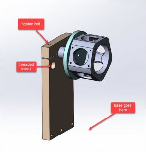
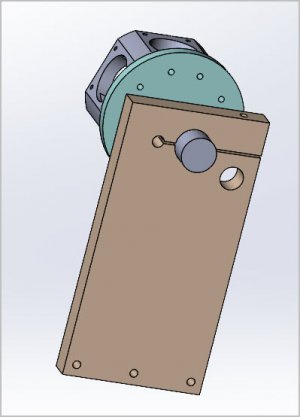
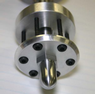
My pic is still in camera but I made this rotisserie contraption mostly to help with assembly. Hopefully makes sense. The idea is I can rotate the engine to any position, lock it in position & work on one cylinder at a time in upright mode for all the fiddly parts. At this point the rear manifold is off so the plate just mounts to my crankcase bolt pattern. Except for the 0.75" aluminum axle, its just MDF so wont hurt my feelings if it doesn't work out. I kind of have 2 competing ideas for a motor mount otherwise I would have designed it to double as a display stand with manifold on, but cross that bridge when I get there.
 

Attachments

  • EDT-2022-02-28 10.52.53 PM.jpg
    EDT-2022-02-28 10.52.53 PM.jpg
    42.5 KB · Views: 21
  • SNAG-2022-02-28 11.05.54 PM.jpg
    SNAG-2022-02-28 11.05.54 PM.jpg
    28.3 KB · Views: 13
Just some food for thought. My engine has a conical split collet on the crankshaft which fits a drive washer plate. The prop is drilled for retention bolts & spinner nut screws on CS threads. This kind of collectively goes round with my RC experience although I'm not so sure about electric starting (re thread direction).
 

Attachments

  • IMG_6885_edited-1.jpg
    IMG_6885_edited-1.jpg
    30.1 KB · Views: 11
  • IMG_7201_edited-1.jpg
    IMG_7201_edited-1.jpg
    194.2 KB · Views: 12
  • IMG_6897_edited-1.jpg
    IMG_6897_edited-1.jpg
    42.4 KB · Views: 14
Just some food for thought. My engine has a conical split collet on the crankshaft which fits a drive washer plate. The prop is drilled for retention bolts & spinner nut screws on CS threads. This kind of collectively goes round with my RC experience although I'm not so sure about electric starting (re thread direction).

I was wondering about this ---- the thread direction tends to tighten the prop nut when the engine is running, but starting it using that nut tends to loosen it and spin it off. I've never really played around with model airplane motors before, so I figured I just have some learning to do.

I suppose if the prop nut keeps spinning off I'll have to do that through-bolt style thing. I like the looks of it at least.

I went through this thread start to finish last night, what a fantastic read. Amazing job and thank you so much for sharing.

Thanks for the kind words! My goal is to finish around mid-summer, hopefully fire it up for a 4th of July BBQ or thereabouts. Lots of work yet to get done, but closer every week.
 
Well, I took a bit of a break this week from machining to work on designing a completely unnecessary control panel for the glow plugs.

At their very simplest, the glow plugs are just glorified toasters, which convert about 3A of of electricity at about 1.5V DC into heat. The minimum viable solution for powering them is to just hook up a regular alkaline battery to the glow plugs and let'em rip.

There are some more advanced control circuits on the market which pulse the power, thereby saving some battery life (or weight).

I'm opting for something completely different ------ A LAUNCH CONTROL CONSOLE!!!

I've got a 4.5-year-old son who is obsessed with rockets / airplanes / etc. So I figure I'd make a control box chock full of switches (some, of course, with obligatory safety flip-up cover), volt meters, ammeters, relays, LEDs, rotary switches, etc. for him to play with. All the while, everything will be completely functional in turning on/off individual glow plugs, and monitoring both current draw through and voltage across each of the glow plugs individually as well as all of the glow plugs overall.

A few of the components have come in so far, but most of them are on the slow boat from China with the customary ETA ranging from a couple weeks to a couple months. Here's what I've got so far:

1646795996298.jpeg


And here's the control circuit I've preliminarily designed. I'm sure there will be changes as I start to mock up the circuit, but it should be pretty close.
1646796068775.jpeg


Side note: I've spent wayyyyy too many hours on this. But that's okay. I'll include an estimate of hours once I make an 'official' post on the design and build of the console.
 
Oh man, we will need to talk at some point. I'm somewhat of an electrical Neanderthal. I mean I can solder & assemble but not design circuits. I've been collecting notes on multi-cylinder glow drivers for a while now. I have lots of experience running RC & have seen the benefit of the 'good' glow drivers, but those are all single cylinder style.

I've attached the typical verbiage from OS (in this case 7-cyl radial). I haven't run their multi-cylinders but they kind of have the same generic recommendation. The recommend 1.2v and nominally ~3A per cylinder, so ~20A capability. This was rather a pain from an airborne weight perspective. I think most guys were soldering up round cells (NiCd or NiMH) in parallel. As I understand it, this was more like maintenance glow. The engine was running/airborne & you could turn auxiliary glow on & off presumably for idle reliability. Now whether people actually started with the same battery configuration I get mixed hits. I've also seen some bench runner with a big battery or power supply. I know that my meter always read higher voltage on the pulse/modulated type single cylinder igniters. But OTOH I have also used those cheesy glow drivers which are basically a single cell connected to the clip. On those I think the cell capacity is relatively large. I seem to recall like 2200-3500 maH per cell? So likely better match to C-rating if the plug is wet & draws more current, less voltage suppression under load. Now there are all kinds of great lithium based batteries but all elevated nominal voltage, say 3.5v for ion or close to 4v for polymer. But I cant think of a good way to split the voltage per plug if you were targeting say 2v max. Unless you had regulators which should probably be 4-5A rated. And that concludes my entire electrical knowledge LOL

Anyways, you look like you know what you are doing so I'll be anxiously waiting to see how this develops. One feature I thought might be useful is to have some degree of control per cylinder. Like a knob or pot that allows this plug gets 1.35V & that plug gets 1.20V. Because the lower cylinders see to run richer, everybody says that referencing a bit more smoke & slightly cooler temps.
 

Attachments

  • SNAG-2022-03-08 11.03.02 PM.jpg
    SNAG-2022-03-08 11.03.02 PM.jpg
    126.3 KB · Views: 11
  • SNAG-2022-03-08 11.03.10 PM.jpg
    SNAG-2022-03-08 11.03.10 PM.jpg
    175.4 KB · Views: 11
  • SNAG-2022-03-08 11.04.28 PM.jpg
    SNAG-2022-03-08 11.04.28 PM.jpg
    169.2 KB · Views: 11
If one powers two devices in series, each one will get half the voltage. This assumes the load is resistive, and the glow plugs are electrically isolated from the head. Three glow plugs in series, then each one receives 1/3 the voltage. N in series, each one receives 1/N volts.

If one glow plug goes out, then the series chain is broken, much like old Christmas lights. (One bulb out, and the whole string goes dark!)

Maybe this helps.
 
Glow plugs are common ground to engine.

So one could connect battery hot to plug one, battery return to plug 2 resulting in 2 in series.

However, odd number of plugs prevents that trick.

Another method would be switching.

Imagine the walking lights you see on casinos and theaters.

You can get a simple TTL chip, used before and cannot remember number, but it takes clock signal in and it goes out on sequential legs.

A simple 555 chip sources the clock.

The output of the counter chip drives transistor to provide current gain t glow plug.

Increase speed to maybe 2kc or so for demonstration.

Ealvery glow plug will be on but no more than 1 at a time so current of one glow plug constant but switching between all.

Dwell time may matter.

A cap on transistors could allow hang time but increase battery drain.

Complicated but something to tinker with.

Sent from my SM-G781V using Tapatalk
 
Oh man, we will need to talk at some point. I'm somewhat of an electrical Neanderthal. I mean I can solder & assemble but not design circuits. I've been collecting notes on multi-cylinder glow drivers for a while now. I have lots of experience running RC & have seen the benefit of the 'good' glow drivers, but those are all single cylinder style.

I've attached the typical verbiage from OS (in this case 7-cyl radial). I haven't run their multi-cylinders but they kind of have the same generic recommendation. The recommend 1.2v and nominally ~3A per cylinder, so ~20A capability. This was rather a pain from an airborne weight perspective. I think most guys were soldering up round cells (NiCd or NiMH) in parallel. As I understand it, this was more like maintenance glow. The engine was running/airborne & you could turn auxiliary glow on & off presumably for idle reliability. Now whether people actually started with the same battery configuration I get mixed hits. I've also seen some bench runner with a big battery or power supply. I know that my meter always read higher voltage on the pulse/modulated type single cylinder igniters. But OTOH I have also used those cheesy glow drivers which are basically a single cell connected to the clip. On those I think the cell capacity is relatively large. I seem to recall like 2200-3500 maH per cell? So likely better match to C-rating if the plug is wet & draws more current, less voltage suppression under load. Now there are all kinds of great lithium based batteries but all elevated nominal voltage, say 3.5v for ion or close to 4v for polymer. But I cant think of a good way to split the voltage per plug if you were targeting say 2v max. Unless you had regulators which should probably be 4-5A rated. And that concludes my entire electrical knowledge LOL
This is literally my first interaction with glow plugs, so I'm not all that far beyond you.

The circuit may look complicated, but the crux of it is to do exactly what the OS manual says with a few "D" size alkaline batteries --- wire them in in parallel to each of the glow plugs. The glow plugs each see about 1.2-1.5V, and I'll use enough batters such that they get sufficient current.

The switches, voltmeter, ammeters, etc. are just fluff.

This will be strictly for bench use. If it ever ends up flying, I'll probably come up with a different solution.


Anyways, you look like you know what you are doing so I'll be anxiously waiting to see how this develops. One feature I thought might be useful is to have some degree of control per cylinder. Like a knob or pot that allows this plug gets 1.35V & that plug gets 1.20V. Because the lower cylinders see to run richer, everybody says that referencing a bit more smoke & slightly cooler temps.
This is a great idea. I played around today with the idea and looked up some potential components to make it work.

There don't seem to be any high-amperage voltage regulators on the market that can output anything less than 1.25V. If I were to make at adjustable, I'd want to see something like 0.9-1.5V or so, so the 1.25V limit doesn't get down low enough.

Using an active voltage conversion circuit may be a possibility, but it's beyond Version 1.0. Maybe next time.


If one powers two devices in series, each one will get half the voltage. This assumes the load is resistive, and the glow plugs are electrically isolated from the head. Three glow plugs in series, then each one receives 1/3 the voltage. N in series, each one receives 1/N volts.
They'll be wired in parallel to a 1.2-1.5V alkaline battery pack.

The glow plugs are all grounded to the motor anyway, so no real way to wire them in series.


Another method would be switching.

A simple 555 chip sources the clock.
If I go with a 'smart' solution down the road, I'll just use a PIC/Arduino/Raspberry Pi.

I've used 555s in the past, but MCUs these days are just too easy.
 
Episode 25 || Propeller Driver Assembly

A few small bits here for driving the prop. Not too challenging, but ties everything together nicely.
1647115258924.png 1647115273511.png


Prop Hub
Nothing special about this part. Just a bit of lathe turning and a tapered bore at 10-degrees per side. None of the dimensions are critical either, so I whipped it out in a hurry.
1647115296937.jpeg 1647115346978.jpeg


Hub Cone
Nothing too complex about this little steel cone either. It’s got a reamed ID to match the crankshaft, and a tapered OD to match the prop hub.
1647115373518.jpeg 1647115389654.jpeg


I then used a jeweler’s saw to add a slit, so that when the propeller nut is tightened down, the prop hub squeezes the hub cone down onto the crankshaft. Not shown: I also added a slit about 75% of the way through at 180-degrees opposite the full slit. I wasn’t getting enough ‘bight’ on the crankshaft with just the slit on one side.
1647115417071.jpeg 1647115432488.jpeg


Propeller Nut
Here we’ve got the pièce de résistance!

There were no drawings of this part in the set of Edwards drawings I’ve got, so I just sized it in Fusion to look about right. It’s got a parabolic shape with a maximum OD about 1.75” and is about 1.5” long.

Order of operations on the part is key. After forming the parabolic front side, there’s no way to hold it. So I started by facing off the back side, then drilling and tapping it 5/16"-24 to match the crankshaft.
1647115451965.jpeg 1647115468135.jpeg


Then ‘off camera’ with a scrap of aluminum, I turned up a threaded arbor to hold the propeller nut for work on the parabola.
1647115488457.jpeg


I used Excel to discretize the parabola at an ‘axial’ spacing of 25 thou to get the appropriate infeed. With that I basically had a really coarse CNC program, and I got to work. (Sorry for the crappy ‘screenshot’.) Axial steps of 25 thou worked great. They captured enough detail but it wasn’t overly cumbersome to perform.
1647115513665.jpeg 1647115526707.jpeg


And I just kept at it until I reached the end.
1647115545142.jpeg 1647115559591.jpeg


I took everything down to a smooth profile with a regular hand file, and finally finished it off with some emery paper and WD40.
1647115584174.jpeg 1647115601493.jpeg


It just unscrewed straight off the mandrel and was a perfect addition to the motor!
1647115618603.jpeg


I’ve seen some airplane motors with serrations on the hub and prop nut. I thought about doing that sort of thing --- even included it in my Fusion model --- but I just didn’t end up doing it. I suppose I might add some sandpaper or something if things start slipping while it’s running.


TIME ON PROPELLER DRIVER ASSEMBLY: 6.0 hours
CUMULATIVE TIME: 408 hours
 
Last edited:
Back
Top