-
Welcome back Guest! Did you know you can mentor other members here at H-M? If not, please check out our Relaunch of Hobby Machinist Mentoring Program!
You are using an out of date browser. It may not display this or other websites correctly.
You should upgrade or use an alternative browser.
You should upgrade or use an alternative browser.
Edwards Radial 5 build thread --- PHOTOS!
- Thread starter JRaut
- Start date
- Joined
- Mar 9, 2018
- Messages
- 465
Episode 27 || Oil Sump and Filter
I made quick work of the oil dry sump and oil filter assembly, which is bolted to the underside of the crankcase. Oil drips down through the cam housing and crank case into the oil sump, is filtered through a brass mesh filter screen, then gets pumped back to the reserve tank by the oil pump I discussed in the last post. Oil drips down on the ‘front half’ and gets sucked out on the ‘back half.’
I didn’t model the filter in Fusion, but it lives right in the middle. The drawings call for a bit of brass mesh filter fabric to just be epoxied in place. That seems like a bit of a clumsy solution, so I opted to make a little removable/cleanable filter cartridge instead. It didn't turn out great, as you'll see. But it's probably good enough.


Oil Sump Body
Pretty straightforward part here. I started by squaring a piece of 6061 aluminum up on the Bridgeport, then ‘drilled’ a couple holes using a ball end mill which will accommodate the sides of the filter cartridge.


Then I roughed out the main pocked by plunging with a 1/4” two-flute flat-bottom end mill.

Instead of using a boring head or bolting it up to my rotary table, I used the very modest early-1980s-vintage two-axis CNC capabilities of my Bridgeport to complete the circular pocket. Turned out great.


Then I used the same 1/8” ball end mill from before to complete the bottom of the filter cartridge pocket.

A couple bolt holes through the top and one hole in the side for a bit of brass tube and she’s good to go. Same as before, I used a dab of Loctite 603 to help hold the tube in place. (NOTE: After bolting this to the motor, I realize that the brass tube is too close to the base of one of the jugs to get a bit of tube on there. I'll have to replace this piece with one that's got a 90* bend in it. I'll do that some other time.)


Oil Filter Cartridge
As stated in the beginning of this post, the drawings call for the brass filter mesh to just be epoxied in place. I think that’s dumb. So here’s my take on a removable filter cartridge. It looked a lot better in my brain; you'll see.
I started off with four bits of the same 1/8” OD brass tube I’ve been using everywhere else, and a bit of #100 mesh (0.006” openings) brass filter fabric I scored from McMaster. Everything is well oversized here; the filter cartridge ends up being pretty darn tiny in the end.

I then trimmed the four tubes to the correct length on the lathe. Then while being held in a little Starrett pin vise, I used a hand file to chamfer each end at about 45 degrees. A Dremel with a 0.025”-wide slitting blade worked great to make a length-wise slot in each of the tubes.


I wasn’t sure what to use to join everything together --- epoxy, CA glue, solder, etc. I opted for silver solder, as I had it on hand.

After cleaning things up best I could and adding a bit of flux to the insides of the tubes, I soldered one side on at a time until I got all 4 on there. It ain’t pretty, that’s for sure. Maybe epoxy would have been better? Anyway, this is how it’s going to be, getting too close to the end to get bogged down in remaking parts like these.

If I were to do it again, in addition to trying something other than solder, I think I’d try to use 1/16” OD tube instead of 1/8” OD and modify the pocket in the sump body accordingly. While the 1/8” tube is indeed pretty tiny on a regular human being scale, it seems a bit too bulky with the cartridge complete.
Anyway, it’s good enough. Let’s just move on.
TIME ON OIL SUMP AND FILTER: 4.0 hours
CUMULATIVE TIME: 424 hours
I made quick work of the oil dry sump and oil filter assembly, which is bolted to the underside of the crankcase. Oil drips down through the cam housing and crank case into the oil sump, is filtered through a brass mesh filter screen, then gets pumped back to the reserve tank by the oil pump I discussed in the last post. Oil drips down on the ‘front half’ and gets sucked out on the ‘back half.’
I didn’t model the filter in Fusion, but it lives right in the middle. The drawings call for a bit of brass mesh filter fabric to just be epoxied in place. That seems like a bit of a clumsy solution, so I opted to make a little removable/cleanable filter cartridge instead. It didn't turn out great, as you'll see. But it's probably good enough.
Oil Sump Body
Pretty straightforward part here. I started by squaring a piece of 6061 aluminum up on the Bridgeport, then ‘drilled’ a couple holes using a ball end mill which will accommodate the sides of the filter cartridge.
Then I roughed out the main pocked by plunging with a 1/4” two-flute flat-bottom end mill.
Instead of using a boring head or bolting it up to my rotary table, I used the very modest early-1980s-vintage two-axis CNC capabilities of my Bridgeport to complete the circular pocket. Turned out great.
Then I used the same 1/8” ball end mill from before to complete the bottom of the filter cartridge pocket.
A couple bolt holes through the top and one hole in the side for a bit of brass tube and she’s good to go. Same as before, I used a dab of Loctite 603 to help hold the tube in place. (NOTE: After bolting this to the motor, I realize that the brass tube is too close to the base of one of the jugs to get a bit of tube on there. I'll have to replace this piece with one that's got a 90* bend in it. I'll do that some other time.)
Oil Filter Cartridge
As stated in the beginning of this post, the drawings call for the brass filter mesh to just be epoxied in place. I think that’s dumb. So here’s my take on a removable filter cartridge. It looked a lot better in my brain; you'll see.
I started off with four bits of the same 1/8” OD brass tube I’ve been using everywhere else, and a bit of #100 mesh (0.006” openings) brass filter fabric I scored from McMaster. Everything is well oversized here; the filter cartridge ends up being pretty darn tiny in the end.
I then trimmed the four tubes to the correct length on the lathe. Then while being held in a little Starrett pin vise, I used a hand file to chamfer each end at about 45 degrees. A Dremel with a 0.025”-wide slitting blade worked great to make a length-wise slot in each of the tubes.
I wasn’t sure what to use to join everything together --- epoxy, CA glue, solder, etc. I opted for silver solder, as I had it on hand.
After cleaning things up best I could and adding a bit of flux to the insides of the tubes, I soldered one side on at a time until I got all 4 on there. It ain’t pretty, that’s for sure. Maybe epoxy would have been better? Anyway, this is how it’s going to be, getting too close to the end to get bogged down in remaking parts like these.
If I were to do it again, in addition to trying something other than solder, I think I’d try to use 1/16” OD tube instead of 1/8” OD and modify the pocket in the sump body accordingly. While the 1/8” tube is indeed pretty tiny on a regular human being scale, it seems a bit too bulky with the cartridge complete.
Anyway, it’s good enough. Let’s just move on.
TIME ON OIL SUMP AND FILTER: 4.0 hours
CUMULATIVE TIME: 424 hours
Last edited:
- Joined
- Nov 8, 2016
- Messages
- 7
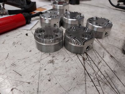
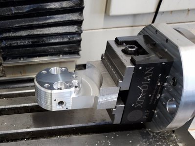
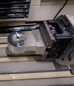
Started working on the heads. Recently DIY'd a 4th for my Tormach so it is nice to cheat and reduce 8 setups to 1. Still got to bore the bottom for the valve cages and tab off the part. Will do the spark plug hole and fins in a standard vise. Changed the design by adding a 1/8" radius to the top just so it doesn't look so blocky.
Attachments
Last edited:
- Joined
- Mar 9, 2018
- Messages
- 465
Episode 28 || Intake Manifold and Cover
The intake manifold and cover were pretty fun to machine, as I got to break out my rotary table and use a bit of the modest CNC capabilities of my Bridgeport 2-axis EZ-Trak. The manifold bolts to the rear cover of the motor and feeds the brass intake pipes (not modeled in Fusion). The cover bolts to the manifold and accepts the carburetor.


I had to wait to make these until I chose/purchased a carburetor, and finally did so. The drawings call for a Perry #302 or #205; the model numbers have changed over the years so there is no such thing as those part numbers any longer. Based on information gleaned from the drawings (principally the dimensions of the manifold cover) I narrowed down my selection to a handful of viable options from Perry’s extensive list of models from their website. It seems like the Edwards drawings are best compatible with the current model No. 2100. The kind gentleman running the show told me that he didn’t have a No. 2100 in stock, but the No. 2400 is identical except for the OD of the mounting spigot, so that’s what I bought. Cost me $58 delivered -- far cheaper than I’d expected.
Intake Manifold
This part looks a bit complex, but it’s not difficult to make if you’ve got the right tooling and spend the time to get the setup correct. I started at the lathe --- turned the OD to approximate size and bored out the inside. I’d have started with a smaller piece of stock, but this is what I had on hand.


With the part still in my (awesome) 6-jaw chuck, I mounted it up to my 12” rotary table oriented in the vertical position over at my Bridgeport. Then proceeded to mill the 5 flats to final size. Size isn’t critical, but it’s nice to get it right.


Then it’s just a matter of blasting through all the holes and O-ring bores.

With the part (still) in the chuck, I clamped my chuck in my 6” vise by grabbing some flats I previously milled in the back-plate for exactly this purpose. Drilled some holes in the end to be tapped 2-56.


I parted off the manifold back at the lathe to final dimension. Then hand-tapped all 14 of the 2-56 holes over at my bench vise. No taps were broken in the making of this part.

Completely Unrelated
I took my kids to a strange/rad local museum (the Bakken in Minneapolis), where I saw perhaps the worst piece of art I’ve ever seen anyone trying to sell. No copyright infringement intended.

Manifold Cover
Another straightforward part if you’ve got the right tooling and setup. I start by turning the 3/4” spigot that tucks into the 3/4” bore in the manifold. Also turned the OD to final size and parted it off.

I used a 5C collet block with a 3/4” collet to hang on to the spigot. I clamped the setup vertically in my milling vise and centered things up.

I’ve mentioned it a bunch of times in past posts, but I’ve got some simple 2-axis CNC capabilities at my Bridgeport. I used that to mill the OD of the offset spigot --- much easier than setting it up on the rotary table. I took too aggressive a cut the first go-round and threw the part; luckily I didn’t scrap it so I really babied it the rest of the way.

After I got to final depth on the spigot, I drilled and reamed the same diameter as the carburetor throat, then milled a counterbore to accept the carb’s spigot.


Then it was just a matter of drilling 4 clearance holes for the 2-56 mounting screws, and drilling/tapping in the side of the spigot for a set screw to hold the carb in place.


After some cleanup and debur of the parts, the intake manifold assembly is all set.

I’ve spent the past couple weeks building a tube bender for the intake/exhaust runners. So those will be next on my list.
TIME ON INTAKE MANIFOLD AND COVER: 8.0 hours
CUMULATIVE TIME: 439 hours
The intake manifold and cover were pretty fun to machine, as I got to break out my rotary table and use a bit of the modest CNC capabilities of my Bridgeport 2-axis EZ-Trak. The manifold bolts to the rear cover of the motor and feeds the brass intake pipes (not modeled in Fusion). The cover bolts to the manifold and accepts the carburetor.
I had to wait to make these until I chose/purchased a carburetor, and finally did so. The drawings call for a Perry #302 or #205; the model numbers have changed over the years so there is no such thing as those part numbers any longer. Based on information gleaned from the drawings (principally the dimensions of the manifold cover) I narrowed down my selection to a handful of viable options from Perry’s extensive list of models from their website. It seems like the Edwards drawings are best compatible with the current model No. 2100. The kind gentleman running the show told me that he didn’t have a No. 2100 in stock, but the No. 2400 is identical except for the OD of the mounting spigot, so that’s what I bought. Cost me $58 delivered -- far cheaper than I’d expected.
Intake Manifold
This part looks a bit complex, but it’s not difficult to make if you’ve got the right tooling and spend the time to get the setup correct. I started at the lathe --- turned the OD to approximate size and bored out the inside. I’d have started with a smaller piece of stock, but this is what I had on hand.
With the part still in my (awesome) 6-jaw chuck, I mounted it up to my 12” rotary table oriented in the vertical position over at my Bridgeport. Then proceeded to mill the 5 flats to final size. Size isn’t critical, but it’s nice to get it right.
Then it’s just a matter of blasting through all the holes and O-ring bores.
With the part (still) in the chuck, I clamped my chuck in my 6” vise by grabbing some flats I previously milled in the back-plate for exactly this purpose. Drilled some holes in the end to be tapped 2-56.
I parted off the manifold back at the lathe to final dimension. Then hand-tapped all 14 of the 2-56 holes over at my bench vise. No taps were broken in the making of this part.
Completely Unrelated
I took my kids to a strange/rad local museum (the Bakken in Minneapolis), where I saw perhaps the worst piece of art I’ve ever seen anyone trying to sell. No copyright infringement intended.
Manifold Cover
Another straightforward part if you’ve got the right tooling and setup. I start by turning the 3/4” spigot that tucks into the 3/4” bore in the manifold. Also turned the OD to final size and parted it off.
I used a 5C collet block with a 3/4” collet to hang on to the spigot. I clamped the setup vertically in my milling vise and centered things up.
I’ve mentioned it a bunch of times in past posts, but I’ve got some simple 2-axis CNC capabilities at my Bridgeport. I used that to mill the OD of the offset spigot --- much easier than setting it up on the rotary table. I took too aggressive a cut the first go-round and threw the part; luckily I didn’t scrap it so I really babied it the rest of the way.
After I got to final depth on the spigot, I drilled and reamed the same diameter as the carburetor throat, then milled a counterbore to accept the carb’s spigot.
Then it was just a matter of drilling 4 clearance holes for the 2-56 mounting screws, and drilling/tapping in the side of the spigot for a set screw to hold the carb in place.
After some cleanup and debur of the parts, the intake manifold assembly is all set.
I’ve spent the past couple weeks building a tube bender for the intake/exhaust runners. So those will be next on my list.
TIME ON INTAKE MANIFOLD AND COVER: 8.0 hours
CUMULATIVE TIME: 439 hours

- Joined
- Nov 25, 2015
- Messages
- 8,284
Pics of your home made bender. Is that AL or Stainless. Looks like stainless...Started playing around with my newly-made tube bender to make some test intake runners.
After a bunch of trials, I think I'm dialing into a winning formula.
View attachment 403093
- Joined
- Mar 9, 2018
- Messages
- 465
Brass actually. The color of the workbench screws with the color balance of my iPhone camera I think.Pics of your home made bender. Is that AL or Stainless. Looks like stainless...
The bender is the kit from Hemningway Kits:
Tube Bender - hemingwaykits.com
Unique projects for the small workshop owner. Please browse our Toolroom and Engine Bay for our latest project kits.
www.hemingwaykits.com
I'll show more pictures of the whole setup and operation once I finish up all the headers.