

-
Welcome back Guest! Did you know you can mentor other members here at H-M? If not, please check out our Relaunch of Hobby Machinist Mentoring Program!
You are using an out of date browser. It may not display this or other websites correctly.
You should upgrade or use an alternative browser.
You should upgrade or use an alternative browser.
Edwards Radial 5 build thread --- PHOTOS!
- Thread starter JRaut
- Start date
Here is my alum solution saga. It went from bad to worse. Not sure what your alloy was, but mine was 2024 btw.
 www.homemodelenginemachinist.com
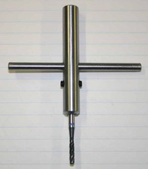
In hindsight it was my own pilot hole error using the tapping head that lead to the break. Now what I use on finicky fine threads is self made tap holder from drill rod. Easy & quick to swap in the drill chuck when the part is still in position, the jaws are just a smidge loose on the body & it guides into the hole perfectly aligned. The tommy bar can be slid in if required.
I figure my engine is ~70% complete now, most of the tough jobs are behind me, so I'll probably start a build thread on HMEM. But I've been posting some abbreviated updates on our local forum here if you're interested

 canadianhobbymetalworkers.com
Amyways, look forward to your continued progress!
broken tap in aluminum cranckase
Dangit! 2 holes away from completion & I broke an M3 tap. I really cant say how, the preceding ones went perfectly fine & I did all the holes & tapping operation identically. It was a brand new, good quality tap, chip ejecting style which I've had excellent good results with in the past. Lots of...
www.homemodelenginemachinist.com
In hindsight it was my own pilot hole error using the tapping head that lead to the break. Now what I use on finicky fine threads is self made tap holder from drill rod. Easy & quick to swap in the drill chuck when the part is still in position, the jaws are just a smidge loose on the body & it guides into the hole perfectly aligned. The tommy bar can be slid in if required.
I figure my engine is ~70% complete now, most of the tough jobs are behind me, so I'll probably start a build thread on HMEM. But I've been posting some abbreviated updates on our local forum here if you're interested
Radial engine build
Some work-in-progress pics of my current project. It’s a 5-cylinder 4-stroke model radial engine, 24mm bore x 22mm stroke 50cc total displacement. Uses RC methanol based fuel & glow plug ignition. About 950-5500 rpm. I bought (2d-paper) plans from a builder in Germany. This is my first attempt...
canadianhobbymetalworkers.com
Amyways, look forward to your continued progress!
Attachments
- Joined
- Mar 9, 2018
- Messages
- 465
Seems like our alum experiments suffered similar fates. Weird how it works so well for some, but not all for others.Here is my alum solution saga. It went from bad to worse. Not sure what your alloy was, but mine was 2024 btw.
Similar to you, I used my junker crankcase as a test bed for using other methods to remove the tap. I had EXCELLENT success (1) using a ball-end carbide end mill to get rid of all the jagged stuff at the top of the tap right where it broke off, then (2) using a coated 1/16 HSS center-cutting endmill to plunge right down through the broken tap. Worked like a charm.
I would have used a carbide endmill the whole way through, but I didn't have one small enough. Even had to borrow the coated 1/16 endmill from a friend. So next time I break a small tap, I know exactly what I'm reaching for.
WOW! Incredible looking build you've got going there! This is by far and away the most complex project I've undertaken to date. So I'll be quite happy if I'm anywhere in the ballpark of what you're putting together. I think I'll pick your brain a bit when I'm working on fitting my cylinder barrels / sleeves.I figure my engine is ~70% complete now, most of the tough jobs are behind me, so I'll probably start a build thread on HMEM. But I've been posting some abbreviated updates on our local forum here if you're interested
- Joined
- Mar 9, 2018
- Messages
- 465
For everything I've tapped since I broke off the #4-40 in the crankcase, I've just been using my Bridgeport in neutral and spinning the spindle by hand, at least to get it started straight. It's a bit cumbersome at times, so perhaps I'll do something like this some day... down the road...Sorry to hear that! Maybe the tap was so small there wasn't really enough surface area for a reaction?
Either way, might I suggest making a simple tapping fixture? Seems it'll be useful on this build!
WOW! Incredible looking build you've got going there! This is by far and away the most complex project I've undertaken to date. So I'll be quite happy if I'm anywhere in the ballpark of what you're putting together. I think I'll pick your brain a bit when I'm working on fitting my cylinder barrels / sleeves.
Thanks & anytime respectively.
One thing tends to come up consistently re the Edwards plans & radials in general is the cam timing. The plans are 100% correct but you have to correctly interpret the cam lobe layout coordinates & their orientation. Builders are often at a loss to calculate equivalent inlet/exhaust valve open/valve close events in terms of piston TDC/BDC when timing the gears. Anyways, I think we beat the issue to death in this post. I went through the same exercise on my radial so just extended it to the Edwards parameters. The physical (idler gear) timing work is still ahead of me but at least I think I understand the issues now.
- Joined
- Mar 9, 2018
- Messages
- 465
Episode 7 || Cam Housing (with some CNC!!)
This ought to be a fun one, so buckle up! We explore the use of some basic CNC, and do a little bit of tool and cutter grinding using nothing more than a worn-out bench grinder and an electric drill.
The cam housing bolts up to the front of the crankcase with #6-32 cap screws, and registers on a boss. It’s a nice looking part, forming the aerodynamic cone at the front of the engine.


The main features at the front of the Cam Housing are pretty straightforward, complicated a little bit by a tight tolerance on the bearing housing, and the tapered cone shape at the front. The back/inside and the periphery of the housing are where things get more interesting. There’s a rectangular cutout on the underside which houses the oil pump; there are a series of 10 reamed holes around the periphery (one each associated with the intake and exhaust push rods for the 5 cylinders); and most interestingly, there is a semi-circular undercut on the inside of the housing associated with each of the 10 reamed holes.


The main OD of this part is about 3-3/4” diameter, but I had some 5” diameter stock left over from my first crankcase attempt. So I chucked that up in my 4-jaw and got to roughing out most of the stock. Lots of chips. If memory serves, I was able to take cuts about 0.100” deep or so on my lathe without chatter. I tend to hand feed, as I don’t have a quick change gear box and often feel too lazy to swap out all the gears, particularly if I’ve got it set up for threading I’m anticipating in the near future.


I wish I had grabbed a few photos earlier in the process, but must have forgotten. You get the point --- first rough off the bulk of the stock, then take off the 0.020 or so I left everywhere. Here is the part with all the turning work finished.


I brought it over to my dividing head on the Bridgeport and indicated it in on the 4-jaw chuck, grabbing it by the very small lip that registers to the crankcase. Was careful not to put too much tension on the jaws, so as not to bend or mar the surface. First step at the mill was to mill out the recess along the cone to accept the oil pump. I like to use permanent marker to keep track of my cuts, particularly if I’m taking a break half-way through an operation.


I then drilled and reamed the 10 holes around the periphery, using the dividing head to divide out the divisions, and plenty of WD-40 along the way as a lubricant. Easy peasy.


And NOW, we get to the fun part!
The 10 undercuts on the inside of the housing were a heap of fun to machine. The drawing calls for the undercuts to be a 0.200” deep semi-circle with a full diameter of 1.500”, and a 1/8” groove width. This could probably have been done by directly plunging with a cutter purpose-built for the job; I didn’t want to go that route for three reasons: (1) I was worried about chatter, as that’s a lot of cutting surface to be taking in one bite, (2) I certainly didn’t want to find/source the cutter for the job (I did search a little with limited success); and (3) I could use some of the basic CNC capabilities of my Bridgeport for a more enjoyable experience.
First, I had to take a hard look through all my drawers for a cutter that might do the trick. The ideal cutter would look something like a 1/8”-thick woodruff cutter. Problem is, none of the standard woodruff cutters are large enough in diameter to provide enough clearance to get the full 0.200” plunge without interference between the shaft of the cutter and the wall of the cam housing. Well, this is hobby machining, right? So why not use something that’s pretty close, and make it good enough?? I had a nearly perfect cutter on hand with enough clearance for the cut, but the only problem was that it was 5/32” thick rather than 1/8” thick, meaning I would somehow have to take about 0.030” off the thickness. So I fired up my redneck T&C grinder! While the ‘finish grind’ certainly wasn’t anything worth writing home about, I ended up at essentially the exact 0.125” thickness I was looking for, and (more importantly) was able to keep it hollow-ground to prevent rubbing.


I’m fortunate to have in my shop a 1989-vintage Bridgeport with some rudimentary 2-axis CNC capabilities. It uses an EZ Trak control system (the original, not one of the later versions) with servo motors controlling the X and Y axes and glass Acu-Rite scales closing the feedback loop. Now when I say rudimentary, I mean rudimentary. All the ‘programs’ need to be entered manually at the DRO-like control box, and it really can only interpret points, lines, and arcs.* It’s awesome for what it does, but it’s nothing like any of the CNC stuff that folks are doing these days (or even a couple decades ago), not even close.


Programming in a successful toolpath took several different attempts, tons of scratch paper, and lots of time picking off points in my Fusion model. It really wouldn’t have been possible without that model.


Alright, now with everything else done, a good-enough cutter in hand, and a CNC program ‘written’, all that was left to do was make the cuts. I first ran a test cut with a permanent marker chucked up to make sure it was going to cut correctly. Then I chucked up my custom-modified woodruff cutter and let’er rip! I don’t recall exactly, but I think I took about 6 or 8 passes to get to the full 0.200” depth of cut. I had the part bolted down to the table with just one bolt right through the center; time was on my side so I kept the cuts light.


For all of those who may doubt that the modified woodruff cutter was as good as I say it was, here’s a photo of a 0.125” gage block slipping in nicely, and a 0.130” gage block not fitting. No doubt luck was on my side with this one.

Here’s the assembly through completion of the cam housing:

Not a single issue with this part, it turned out way better than I had even expected.
TIME ON CAM HOUSING: 14 hours
CUMULATIVE TIME: 88 hours
*There is a serial interface at the back of the control panel, but I have yet to experiment with feeding it through that port.
This ought to be a fun one, so buckle up! We explore the use of some basic CNC, and do a little bit of tool and cutter grinding using nothing more than a worn-out bench grinder and an electric drill.
The cam housing bolts up to the front of the crankcase with #6-32 cap screws, and registers on a boss. It’s a nice looking part, forming the aerodynamic cone at the front of the engine.
The main features at the front of the Cam Housing are pretty straightforward, complicated a little bit by a tight tolerance on the bearing housing, and the tapered cone shape at the front. The back/inside and the periphery of the housing are where things get more interesting. There’s a rectangular cutout on the underside which houses the oil pump; there are a series of 10 reamed holes around the periphery (one each associated with the intake and exhaust push rods for the 5 cylinders); and most interestingly, there is a semi-circular undercut on the inside of the housing associated with each of the 10 reamed holes.
The main OD of this part is about 3-3/4” diameter, but I had some 5” diameter stock left over from my first crankcase attempt. So I chucked that up in my 4-jaw and got to roughing out most of the stock. Lots of chips. If memory serves, I was able to take cuts about 0.100” deep or so on my lathe without chatter. I tend to hand feed, as I don’t have a quick change gear box and often feel too lazy to swap out all the gears, particularly if I’ve got it set up for threading I’m anticipating in the near future.
I wish I had grabbed a few photos earlier in the process, but must have forgotten. You get the point --- first rough off the bulk of the stock, then take off the 0.020 or so I left everywhere. Here is the part with all the turning work finished.
I brought it over to my dividing head on the Bridgeport and indicated it in on the 4-jaw chuck, grabbing it by the very small lip that registers to the crankcase. Was careful not to put too much tension on the jaws, so as not to bend or mar the surface. First step at the mill was to mill out the recess along the cone to accept the oil pump. I like to use permanent marker to keep track of my cuts, particularly if I’m taking a break half-way through an operation.
I then drilled and reamed the 10 holes around the periphery, using the dividing head to divide out the divisions, and plenty of WD-40 along the way as a lubricant. Easy peasy.
And NOW, we get to the fun part!
The 10 undercuts on the inside of the housing were a heap of fun to machine. The drawing calls for the undercuts to be a 0.200” deep semi-circle with a full diameter of 1.500”, and a 1/8” groove width. This could probably have been done by directly plunging with a cutter purpose-built for the job; I didn’t want to go that route for three reasons: (1) I was worried about chatter, as that’s a lot of cutting surface to be taking in one bite, (2) I certainly didn’t want to find/source the cutter for the job (I did search a little with limited success); and (3) I could use some of the basic CNC capabilities of my Bridgeport for a more enjoyable experience.
First, I had to take a hard look through all my drawers for a cutter that might do the trick. The ideal cutter would look something like a 1/8”-thick woodruff cutter. Problem is, none of the standard woodruff cutters are large enough in diameter to provide enough clearance to get the full 0.200” plunge without interference between the shaft of the cutter and the wall of the cam housing. Well, this is hobby machining, right? So why not use something that’s pretty close, and make it good enough?? I had a nearly perfect cutter on hand with enough clearance for the cut, but the only problem was that it was 5/32” thick rather than 1/8” thick, meaning I would somehow have to take about 0.030” off the thickness. So I fired up my redneck T&C grinder! While the ‘finish grind’ certainly wasn’t anything worth writing home about, I ended up at essentially the exact 0.125” thickness I was looking for, and (more importantly) was able to keep it hollow-ground to prevent rubbing.
I’m fortunate to have in my shop a 1989-vintage Bridgeport with some rudimentary 2-axis CNC capabilities. It uses an EZ Trak control system (the original, not one of the later versions) with servo motors controlling the X and Y axes and glass Acu-Rite scales closing the feedback loop. Now when I say rudimentary, I mean rudimentary. All the ‘programs’ need to be entered manually at the DRO-like control box, and it really can only interpret points, lines, and arcs.* It’s awesome for what it does, but it’s nothing like any of the CNC stuff that folks are doing these days (or even a couple decades ago), not even close.
Programming in a successful toolpath took several different attempts, tons of scratch paper, and lots of time picking off points in my Fusion model. It really wouldn’t have been possible without that model.
Alright, now with everything else done, a good-enough cutter in hand, and a CNC program ‘written’, all that was left to do was make the cuts. I first ran a test cut with a permanent marker chucked up to make sure it was going to cut correctly. Then I chucked up my custom-modified woodruff cutter and let’er rip! I don’t recall exactly, but I think I took about 6 or 8 passes to get to the full 0.200” depth of cut. I had the part bolted down to the table with just one bolt right through the center; time was on my side so I kept the cuts light.
For all of those who may doubt that the modified woodruff cutter was as good as I say it was, here’s a photo of a 0.125” gage block slipping in nicely, and a 0.130” gage block not fitting. No doubt luck was on my side with this one.
Here’s the assembly through completion of the cam housing:
Not a single issue with this part, it turned out way better than I had even expected.
TIME ON CAM HOUSING: 14 hours
CUMULATIVE TIME: 88 hours
*There is a serial interface at the back of the control panel, but I have yet to experiment with feeding it through that port.
Last edited:
- Joined
- Apr 29, 2019
- Messages
- 2,059
I still love it.
But the smart a$$ in me cant resist, How do you hollow grind a 3/32 cutter to exactly .125 thick?
Sorry, had to do it.........
But the smart a$$ in me cant resist, How do you hollow grind a 3/32 cutter to exactly .125 thick?
Sorry, had to do it.........
Episode 7 || Cam Housing (with some CNC!!)
First, I had to take a hard look through all my drawers for a cutter that might do the trick. The ideal cutter would look something like a 1/8”-thick woodruff cutter. Problem is, none of the standard woodruff cutters are large enough in diameter to provide enough clearance to get the full 0.200” plunge without interference between the shaft of the cutter and the wall of the cam housing. Well, this is hobby machining, right? So why not use something that’s pretty close, and make it good enough?? I had a nearly perfect cutter on hand with enough clearance for the cut, but the only problem was that it was 3/32” thick rather than 1/8” thick, meaning I would somehow have to take about 0.030” off the thickness. So I fired up my redneck T&C grinder! While the ‘finish grind’ certainly wasn’t anything worth writing home about, I ended up at essentially the exact 0.125” thickness I was looking for, and (more importantly) was able to keep it hollow-ground to prevent rubbing.
- Joined
- Mar 9, 2018
- Messages
- 465
I still love it.
But the smart a$$ in me cant resist, How do you hollow grind a 3/32 cutter to exactly .125 thick?
Sorry, had to do it.........
I reckoned I'd get a question like that.
First --- I meant 5/32" (0.156), not 3/32" (0.094). Duh. Sure would be hard to grind a 3/32" cutter and wind up at 0.125". (I edited my post above to reflect the actual size.)
Second --- Lots of grinding and checking. Nothing special about the grinder, it's just a regular bench grinder with a horribly dressed wheel and horribly rounded corners (6" diameter, I think). I had the woodruff cutter chucked up in my electric drill and was spinning it the whole time at a good clip.
I initially got most of the meat off the cutter without any special regard to focusing on any particular area. Just wanted to get it in the ballpark.
When it was close, I went at the very periphery of the cutter--right at the edges of the cutting teeth--and got them a hair under 0.125. I figured there was little chance I'd have all the teeth ground the same, so it would probably cut oversize from what I was measuring with my micrometer.
Once I had the tips of the cutting teeth a good size, I just hogged out as much as I could from the center of the cutter. The shape of the grinder wheel is ideal for hollow grinding (well, certainly not ideal; perhaps 'serviceable' is a better word choice...). Just took a lot of focus to try to keep the grinding wheel in the center of the cutter. Small slip-ups, of which there were many, meant I was taking a bite out of a cutting tooth. I mainly used the rounded edge of the wheel rather than the flat-ish front.
I honestly think there was a lot of luck in getting so close to my target size (ended up at 0.130 rather than 0.125, close enough). But you better believe I'll be trying it again if I need to do something similar in the future.
*** Full disclosure: the first thing I tried was chucking up the woodruff cutter in my lathe and going at it with a carbide inserted turning tool. I didn't expect it to work, and I was right. Chipped the cutter immediately.