

-
Welcome back Guest! Did you know you can mentor other members here at H-M? If not, please check out our Relaunch of Hobby Machinist Mentoring Program!
You are using an out of date browser. It may not display this or other websites correctly.
You should upgrade or use an alternative browser.
You should upgrade or use an alternative browser.
Edwards Radial 5 build thread --- PHOTOS!
- Thread starter JRaut
- Start date
- Joined
- Oct 30, 2019
- Messages
- 197
You are not alone, thank you for sharing this!The logical way to create the fins on these cylinder barrels is using a parting tool on the lathe. Now, I’ve always struggled with grooving and parting-off on my lathe. I’ve tried grinding my own parting blades and using store-bought blades. I’ve tried narrow blades (0.040”) and wide blades (0.125”). I’ve tried lining up things to be square by eye, aligning things square using an indicator, and even purposely lining it up off-square. I’ve tried neutral-, left-, and right-cutting geometry. I’ve used high-speed steel, brazed carbide, and carbide inserts. I’ve used the “T” style, and all sorts of other styles. I’ve tried setting the tool on center, slightly above center, and slightly below center. I’ve tried power feeding and hand feeding. I’ve worked with aluminum, brass, bronze, cast iron, mild steel, and alloy steel. I often tighten up my gibs, I always choke up on the tool, and I always set the carriage lock.
Thanks! I aim to please.
I'm certainly open to that, I just don't happen to run in the RC airplane circles so I don't know of anyone looking for a motor currently. The thought of bringing it to a local RC aviation meetup/event has crossed my mind, so perhaps I'll do that once (if) it's operational and reasonably reliable.
Me! me! me!, mail it to me. I am an rc airplane nut. I have dozens of planes and dozens of engines.
- Joined
- Mar 9, 2018
- Messages
- 465
Well, I was hoping nobody would comment on this thread and bring it back to life -- I've made very little progress over the past half-year or so.
Been super busy at work, and just about all my free time these days is (rightly) being consumed by my wife and 2- and 5-year-old kids.
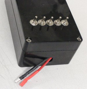
That said, I am finally making some more headway on that 'Launch Control Panel' that I mentioned way back in March 2022.
Busy time of life. Which I can't complain about.
Been super busy at work, and just about all my free time these days is (rightly) being consumed by my wife and 2- and 5-year-old kids.
That said, I am finally making some more headway on that 'Launch Control Panel' that I mentioned way back in March 2022.
Busy time of life. Which I can't complain about.
I don't want to derail your post but I'll drop a few items regarding your To Do list if its helpful. I am approaching Ignition Day myself so don't read too much into any perceived level of useful knowledge. But if anything catches your interest, ask away.
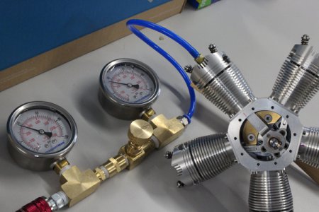
I built a leak down tester, similar to automotive style. So you can test your valve seal & piston ring seal by observing the gage pressures being equal for some time period & listen/locate any hiss. Rather than a (tiny) orifice between the gages I used a needle valve which seems to work. (Yes, I know piston is supposed to be at TDC, I needed one more hand to snap a pic. It wants to 'run' on the bench LOL).
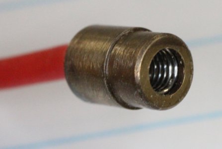
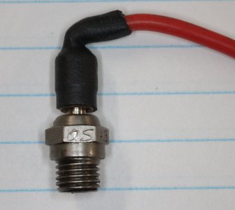
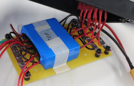
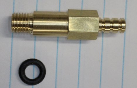
I found these glow plug harnesses on AliExpress which saved me some fiddling around. They use a captive spring retention system which seems to make nice firm contact & electrical continuity. I did test a NIMH cell bank to drive the plugs. They work but you have to keep resistance low & stack up sufficient maH to deliver the current. I subsequently found these dedicated RC glow plug regulators from AliExpress which can accept elevated input voltage & they deliver constant plug voltage at appropriate current. I bought 5 & wired them up in parallel. Its a bit ghetto. Driven by a common RC Lipo battery.
I built a leak down tester, similar to automotive style. So you can test your valve seal & piston ring seal by observing the gage pressures being equal for some time period & listen/locate any hiss. Rather than a (tiny) orifice between the gages I used a needle valve which seems to work. (Yes, I know piston is supposed to be at TDC, I needed one more hand to snap a pic. It wants to 'run' on the bench LOL).
I found these glow plug harnesses on AliExpress which saved me some fiddling around. They use a captive spring retention system which seems to make nice firm contact & electrical continuity. I did test a NIMH cell bank to drive the plugs. They work but you have to keep resistance low & stack up sufficient maH to deliver the current. I subsequently found these dedicated RC glow plug regulators from AliExpress which can accept elevated input voltage & they deliver constant plug voltage at appropriate current. I bought 5 & wired them up in parallel. Its a bit ghetto. Driven by a common RC Lipo battery.
Attachments
- Joined
- Oct 1, 2023
- Messages
- 5
Same here. I’ve had a set of plans for the ageless engines sense 2013 and haven’t started at all. Just keep watching videos of othersWow, this engine looks really cool! I cannot wait to see how it turns out!
- Joined
- Oct 1, 2023
- Messages
- 5
Is it possible to do all of the work on just the lathe?Episode 3 || Crankcase (Attempt 1)
I figured I’d start out with the Crankcase of the Radial 5, since it forms the backbone of the whole motor. It’s quite a complex part to make, requiring several different setups on both the lathe and the mill with a dividing head. And about 60 holes, many of which are tapped #2, #4, or #6.
View attachment 325713
View attachment 325714 View attachment 325715
I started out by chucking up a chunk of 5”-diameter stock in my 4-jaw chuck. A 4”-diameter piece would have worked, but I had some 5” on hand. So it took quite a bit of roughing to get it down to size. Note that there’s a fair amount overhang; that’s because I’m trying to get the crankcase, cam housing, and back plate all out of this one piece and barely have enough length. Would have wasted too much chopping it into three separate chunks.
View attachment 325700 View attachment 325701
You can see in the fusion model that there is an ‘undercut’ deep within the inside of the housing. It proved rather difficult to remove this material, and I had to grind up a trepanning tool to do so. I’ve never ground a trepanning tool, and this one had to have quite some overhang to get deep down in there. It ain’t pretty, but it worked. Sorry for the photo quality, was hard to get a good photo.
View attachment 325703 View attachment 325702
Once I finished roughing everything out, I gave it some time to cool down, then finish turned everything to final size. The central bore accepts a deep groove ball bearing so had to be pretty precise. Lots of chips were made over on the lathe!
View attachment 325716
The next step was to get the finish-turned crankcase mounted up to my dividing head. That wasn’t the easiest process. In an ideal world, I would have parted off the crankcase and bolted it straight to a H/V rotary table / dividing head mounted to my mill. I don’t have one of those. And because of the geometry of the crankcase, I didn’t really see a good way to grab onto it over at the dividing head, so I opted to leave it in the 4-jaw chuck in an attempt to maintain concentricity. My lathe spindle doesn’t match my dividing head spindle, so I had to make an adapter. All that added up to a tremendous amount of stick-out. Not even close to ideal…
View attachment 325704 View attachment 325705
In an attempt to control runout and deflection while milling the flats, I set up a clamping system and indicated in each position. It was a huge hassle, but I got close enough (within a few thou) in every setup.
View attachment 325706 View attachment 325707
Once I had the 10 flats milled to dimension, I drilled, bored, tapped what felt like a million holes.
View attachment 325708 View attachment 325709
BUT!!!
I ended up breaking off a #4-40 tap in the second-to-last hole that required tapping. Huge bummer. More on that in the next post. I reckoned I’d be able to get it out, so I kept on with things.
View attachment 325712
After mounting back on the lathe and parting off, I had just a few more drills / counterbores and it was finished (except for removing the broken tap).
View attachment 325710 View attachment 325717
There were a few issues with the part (I accidentally oversized one hole; broken tap issue, some non-concentric features, etc.), but those were generally on non-critical features. Overall I was pretty proud of what I had accomplished. It was a very complex part and I had knocked it out with pretty darn good success.
Next episode will be on (trying unsuccessfully) to remove the broken tap.
TIME ON CRANKCASE: 22 hours
CUMULATIVE TIME: 48 hours
- Joined
- Oct 1, 2023
- Messages
- 5
Just cut out the web and the rest will fall out. No damage to your threads. Works goodGet a dremmel or high seed pneumatic from HF and the diamond bits or dental burs and carefully cut it out.
Whenever you visit the dentist ask what happens to the old burs as often they are thrown away.
Sent from my SAMSUNG-SM-G930A using Tapatalk