Electric Problems With My Enco 13x40

DJack

Registered
Registered
Joined
Jan 1, 2015
Messages
11
None of the lights worked on my lathe so I changed the bulbs, I used regular 6v auto type bulbs. Still don't work so I checked voltage at the bulbs it shows 12v when it it supposed to be 6v, could be why the bulbs blew out. I checked at the transformer and I have 12 volts at the bulb circuit and 44v at the controll circuit, it is supposed to be 29 volts. I can't see how a transformer could put out more than it is supposed to so I checked some more and found that I had 12v on one side of the bulb and 16v on the other side. No ground so lights can't work. Does anyone know it there is a special type bulb that goes in there? Does anyone have a similar lathe and be willing to check voltage at the transformer? On mine the input to the transformer is on the top, two red wires with 110v each 220v combined, the output is on the botton supposed to be 6v on the white wire and 29v on the red wire. The electrical diagram provided with the lathe is hard to decypher.
Thanks
Dave
PS I ordered a Phase 2 tool holder set from enco today any comments on the phase 2.
 
I cant help you with the electrics on the lathe I have no experience with how they are wired. On the Phase 2 toolpost and holder, you will be fine, if by chance you get a dud, just return it to Enco in first month on their dime. Its not Aloris quality but darn good. I have been trying to kill one for over 10 years and it still works fine.
michael
 
I checked some more and found that I had 12v on one side of the bulb and 16v on the other side.

I assume you are measuring to ground here. What is the voltage across the bulb terminals? And more importantly, what is the loaded voltage (with a bulb installed) across the terminals? Those are some really odd voltages in the system, I've never heard of anything running at 29 volts.

Maybe you can scan or snap a photo of the electrical diagram and post it.
 
What is your input voltage? 120 or 240? What is the setting at the transformer? If the transformer is wired for 120 and you are using 240 this would explain things. Detailed pictures of the electrics would help.
Pierre
 
Yes the voltage was to ground, I never checked across the bulb but I did check it with a bulb in it and it wend down to 2-3 volts on each side of the bulb, again this was to ground. I didn't check across the bulb because I thought I wouldn't get a reading with voltage on both sides. The 29 volts is a control voltage for the magnetic switches that control the motor. The lathe works ok but I worry about the 44 volts damaging the relays. I'll try scanning the wiring diagram, it looks like a scanned copy so I don't know how well it will turn out. The input voltage is 240v but it looks like 2 sets of winding,s in one housing. I'm beginning to think there is an internal short in the windings of the transformer. Parts are not available for this lathe so I'm thinking of trying one with a 24v output and see if it will energize the switches.
 
Typically you have 110 or 220 on one side depending on which connection you use, and 24V (could be more depending on the actual input voltage) on the other side. What "ground" are you talking about? Typically there is no ground connection on the output side; it's just 24V across the output going to the relay. If by "ground" you mean the line ground or the metal frame you'll get odd voltage readings because the output isn't connected there; it just floats. It may show a voltage but if you connect something there it won't work because it pulls it down to near zero.

Likely your bulbs should be 24V if they're bulbs in a standard industrial type switch.

Unless there is a third transformer output... note that 29 - 6 = 23 which is almost 24. 23V at 110 input would be 24V at 115 and 25V at 120. Most relays are good up to 30V.
 
The stock halogen lights on many import lathes are 24V & are 25w or 50w depending on the lamp assy.
 
What "ground" are you talking about? Typically there is no ground connection on the output side; it's just 24V across the output going to the relay. If by "ground" you mean the line ground or the metal frame you'll get odd voltage readings because the output isn't connected there; it just floats. It may show a voltage but if you connect something there it won't work because it pulls it down to near zero.


+1 what FanMan said. Many of the Asian machines do not have the the secondary (24-29 volt side) of the transformer grounded. So you have connect one probe to the common terminal on the output and measure the voltages relative to that, or measure across the coils of relays.
 
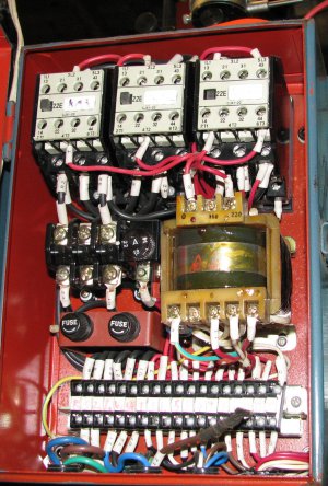
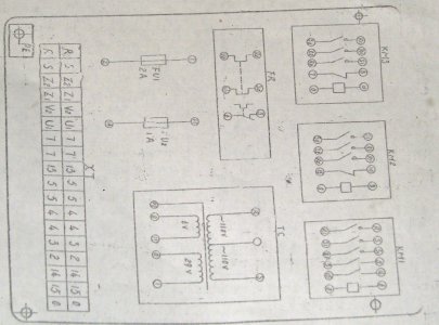
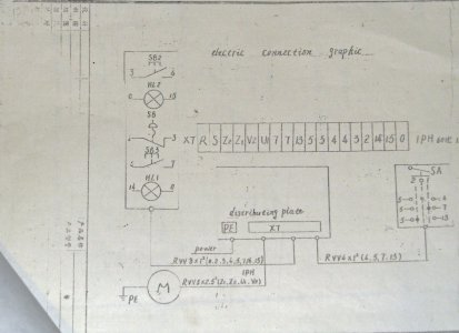
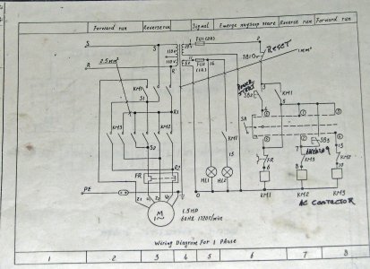
Here are some pictures of the wiring and electrical box. I checked again and I have 243v across the top red terminals, I have 34v from the right red lower wire to the next wire on the transformer (white) and I have 0 volts from the left lower red wire to the white wire. Looks like the transformer might be bad. If I can find some 34 volt bulbs I can switch the lights over to the other side. Or add a 6v or 12v transformer . Hope somebody can use the wiring diagrams, they are for an Enco 110-1342 buillt July 1995.
Thanks for the replies

IMG_0300.JPG IMG_0307_edited-1.JPG IMG_0304_edited-2.jpg IMG_0303_edited-3.jpg
 
I agree, with 0 volt between what is supposed to be 6 volt, and the white wire (common) the transformer may be bad, but this would be unusual. Since the wires come out of the transformer and connect to the terminal block on the transformer, I would be checking for a bad connection on the back of the terminal block.

I was going to say that a 34 volt bulb might be a bit hard to find, but to my amazement they actually make them.

http://www.pinnaclepeaktrading.com/s.nl/it.A/id.5173/.f

http://www.grainger.com/category/mi...d-bulbs/lamps/lighting/ecatalog/N-kigZ1z0mm68
.
.
 
Back
Top