Electro-mechanical assistance needed

T Bredehoft

Active User
H-M Supporter Gold Member
Joined
Dec 27, 2014
Messages
4,056
My propeller machine was made perhaps 30 or more years ago from (probably) used components. It has three motors, one spins the spindle at 10,300 rpm, another moves the table back and forth, at milling speeds, and a third moves the sanding drum (spindle) up and down perhaps once every second. It does this moving a cam at that speed, so the revs of the motor is (I'm guessing) 60 rpm. This motor has stopped working, shutting down production. I have an order for a number of propellers going to England which I don't want to loose.

Below are pictures of the motor.
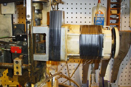
Front view.jpg

This is the "front" of the motor, as viewed from the work station. Its 6 inches long and 3/5 in diameter.
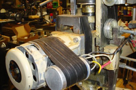
Back view.jpg

And this is the back. The circle on the left end is a fan which spins with the motor.
I assume the aluminum cylinder is a capacitor, which I am concerned about discharging.

When I got the machine the previous owner told me that if they ever stopped I'd have to take them apart and clean the little balls in the end. He was not a machinist, and I'm looking for advice on "What is this motor?" and "How do I fix it?"
I am a tool maker, not a repairman, so any and all suggestions are most welcome.
 
A little more detail on what "stopped working" means. Does not start, does not turn, some sound, no sound, etc. Start with the easy variables to eliminate and check all wire connections. It is amazing how easy something can come loose.

The aluminium can likely contains a capacitor used to get the motor running in the correct direction. This is part of a start circuit. As some % of the full rpm, a centrifugal switch opens disabling the start circuit. When the motor is turned off, you will normally hear a "click" as the centrifugal switch closes ready for the next time you start the motor.

If the centrifugal switch is full of dust it can stay open. The motor will then not operate, but may hum or look to vibrate.

If you try turning on the motor and manually start the rotation and it runs, it is the centrifugal switch which is stuck open.

The centrifugal switch is normally on the fan end of the motor. Try removing the fan cover and blow out the dust with compressed air.
 
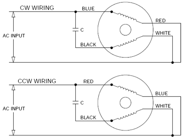
Looks like a standard induction motor with a starter capacitor to me. Will probably have two winding one connected directly across the supply and one in series with teh capacitor. Something like this.
ACP-Mxl%20Wiring%20%28600x450%29.png


First check you have power on the supply cable to the motor.
Next if you can power up the motor and then give the shaft a spin and it will start up then it is the capacitor that needs replacing. The capacitor is normal connecting so it will discharge through the winding when shutdown so stored charge should not be a problem. Just ensure it is turned off and then short the terminals with a screwdriver just to be sure.
Then try checking the winding resistance with a multimeter to make use both winding are intact - no open circuit.

That would be my start.
 
Two quick replies, I should have stated that the motor willl not run if manually turned. I've run a couple of props, by spinning the fan by hand. No run, no joy. This eliminates the starter from the problem, I guess.
How do I check the Cap? I can barely get to look at it as in the lower picture.

Edit: no noise, sometimes there is a minor resistance to turning, ie., as it turns there are stiff positions.
 
I digress - but are induction motor with centrifugal switches common in the US?
I must have had over 30 different single phase induction motors in my shop over the years and I have only ever come across one of them that had a centrifugal start switch. All the others the start capacitor just stays connected (as in my diagrams above). They seem to be talked about as such a common failure mode but I just don't come across them.
Maybe its a voltage thing and there are more advantages to having centrifugal switches on a lower 110Vac supply than on the 240Vav supplies I'm used to?
 
The resistance to turning sound like it may be a bearing seizing which could then of lead to a motor winding burning out. You will need to check the winding resistance/continuity of the motor windings.

From the photo it looks like there are two white and one black wire going into the motor. You should get a small resistance across two of the connections and about double the resistance across the third. If there is a high/infinite resistance anywhere you probably have a burn out (open circuit) winding.

Also check for high resistance between each wire and the motor body - but if you has a short you would of probably blown the circuit breaker and already know about it.
 
Judging from the size of the cap it looks like a capacitor run (also called permanent split-cap) motor so there may not be a starter switch inside.
The cap can be checked with an ohmmeter. With AC power off, disconnect the cap from the circuit (you can just unhook one terminal) and discharge it with a insulated screwdriver. You may get a spark or maybe not. Put your meter on ohms and measure the cap; the meter should show low resistance then move towards infinity. Reverse the test leads and measure again. This is easier with a swinging needle type meter. You should get the same type of readings each time. If the meter shows a short circuit or a permanent open (very high reading) the cap is bad.
Some of the motor wiring looks a bit kludgey- check that too. Maybe a loose connection?
 
Be sure to put your meter back to AC after you do the cap test- you don't want to blow up your meter!
MS
 
I'm no electrician, so this doesn't mean much to me, but I'm reporting as found.

This machine is cobbled together from many parts. it is powered both by 110 VAC and a 12 V battery charger.

The Cap behaves as described above, peaks when touched to .5 (somethings) drops to zero then climbs.

Motor leads. One black wire goes into the motor. Connecting to this wire and either termian of the cap I get an Ohm reading on the 200 Ohm scale of 12. No connection to the body, open circuit.

The power supply;
with power off, the two leads to the motor read 1.5V on a 200 VAC scale, on a 2 VDC scale reads .001-.002
With the power on (motor disconnected lying on work bench) the leads read 200 VAC 3.0 to 4.0 on 2 VDC, .005 to .027.

I'm beginning to wonder if I'm looking in the wrong place.

"He'p Rhonda, he'p get it into my head. "
 
Problem solved, replaced a wire between the off-on switch and the motor. It's lost deep inside a tape wrapped cable, no idea what the problem was.

Having replaced the wire, I also replaced the switch. it was showing an open circuit occasionally.
 
Last edited:
Back
Top