Electronic Lead Screw

ttabbal

H-M Supporter - Gold Member
H-M Supporter Gold Member
Joined
Jun 12, 2017
Messages
2,081
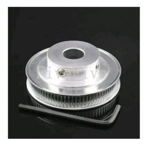
I'm going to attempt to adapt clough42's ELS to my PM1127. I figure I might as well do it publicly in case it ends up being useful for someone else. I have most of the parts now, and have the electronics and servo running on the bench. The first thing I decided to mess with is the rotary encoder. I needed a way to drive it from the spindle. I decided to try adapting one of the GT2 pulleys to replace a change gear. This allows a minimaly invasive connection.
IMG_20190923_232716-870x1160.jpg

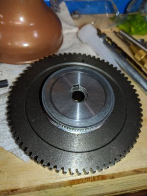
The pulley is a bit thicker than the stock gears. This 80T has enough metal in the middle that I can turn out a shallower section in the middle if needed though.

It started out looking like this..
PhotoPictureResizer_190923_235038460_crop_403x403.jpg

I held the protruding part on top in the chuck, cut the keyway (3/16 HSS blank worked great). Faced the bottom flat. Then gripped the end and parted it off. Then faced the parted side. Note that these are not a single piece. The center is solid, the toothed ring and the two flanges are pressed onto the center.

The spindle is 40 teeth, so the plan is to mate the pulley to an 80 tooth gear. Then use a 40 tooth pulley on the encoder. That should put the encoder at the same RPM as the spindle.

The gear will be held on the stock change gear rack with the stock axle. The encoder I'm planning on building a bracket to mount with t-nuts to the change gear rack where the second gear set would be.
 
That looks like it ought to work. Thinning the timing pulley in the center to the same thickness as the stock gears to get full engagement of the nut is a good idea. I used a 6mm GT2 timing belt to couple the encoder on my ELS project, and replaced the stud gear on my Logan Model 200 with a modified timing pulley. I'm driving the leadscrew with a 15mm wide 3mm pitch belt. You've got all kinds of room under the cover on your lathe to do pretty much anything you want. Keeping the encoder pulley small is a good idea, to keep the mass down. I worried about spring/mass-induced oscillations, but have had no issues. Even 6mm timing belts are very stiff.
 
IMG_20191007_000358-800x600.jpg

Finally got some shop time.

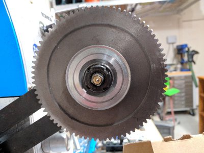
Thinned out the center and mounted the stack on the bar. Looks like it will work.

I also made some T-nuts for the arm to use for mounting the encoder mount. The thread is M6-1.0. The stock nuts have a round center, but the normal shape works fine.
 
PhotoPictureResizer_191013_221900317_crop_2922x1576-730x394.jpg

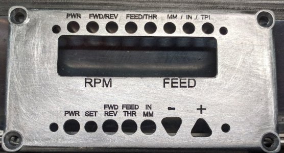
Decided to take a break on the gears and look at the Main control panel. Did some expensive learning on the CNC, but overall I'm happy with it. I didn't see a version with the text, so I used Fusion360 to add it and generate toolpaths. The depth in the top right got a little bit light, but it's good enough to read without hassle.
 
I know little about these modifications. My first thought of where to put a RPM reader would be at the left end of the spindle, or maybe even in the gear box if it does not use flood lubrication. Change gears get moved around a lot, and that may cause extra time to set up the reader with each change. ??
 
Once this modification has been done, there is no longer any need for any change gears, it's all done electronically. As for where to put the encoder, it's on a case by case basis where it should go, since we use a wide variety of lathes.
 
I'm mounting the encoder on the rack that holds the change gears at the moment. The designer put his under the cover on the left as well. Last time he showed it, it was mounted on a magnet from an indicator stand.

I'm planning on putting the servo under there somewhere as well. Probably just wherever is convenient for testing. Then I'll try to find a way to get it mounted in a way that allows me to close the cover. That way I can order the right belt after I have a good spot so I can measure for it.

Thanks for sharing your progress @kb58! Glad to see other takes on setup.
 
Once this modification has been done, there is no longer any need for any change gears, it's all done electronically. As for where to put the encoder, it's on a case by case basis where it should go, since we use a wide variety of lathes.
Doh! I missed that bit of reality... :bang head:
 
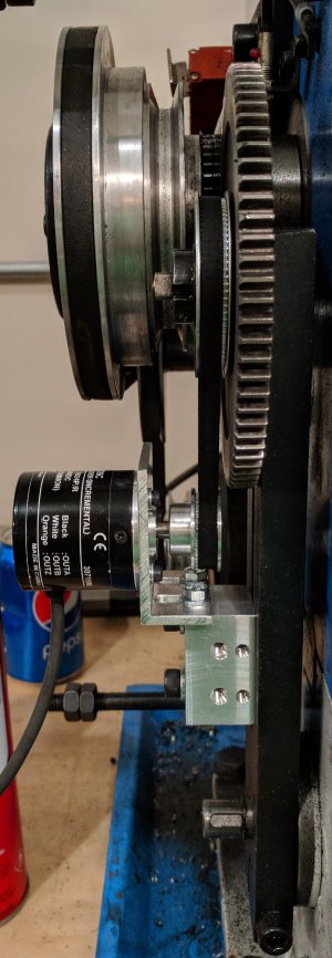
Got some shop time in finally. The encoder is mounted after a couple of, um, test fits. :)

Connected it to the board and tested RPM readout. It worked great. Matched up closely with the onboard gauge across the range. So one down.

The belt in the photo is 280mm long. I wouldn't want to go much longer as it will start interfering with the input pulley at the bottom. I suspect that a 250mm would work, but don't have one on hand to test.

PhotoPictureResizer_191027_160049178_crop_1450x4183-600x1731.jpg
 
Back
Top