Elevator Shaft Issues

Ceej0103

H-M Supporter - Diamond Member
H-M Lifetime Diamond Member
Joined
Feb 14, 2020
Messages
166
Hello everyone...

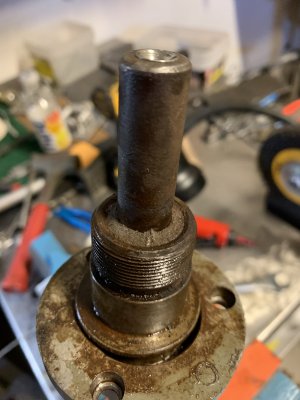
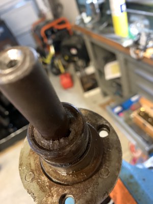
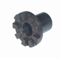
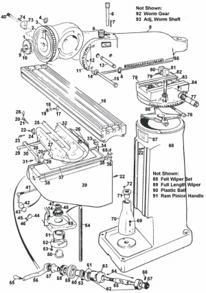
I'm doing a Bridgeport restoration project and ran in to an issue. When I went to pull the gear shaft clutch insert it broke away. Now the portion that slips under the dial holder is seized. I've tried some light prying between the dial holder and bearing retainer ring, I've tried supporting it under the bearing retainer ring and tapping it down on the top of the shaft, I've hit it lightly with the air hammer and a pointed chisel in the shaft's center hole, and I've oiled it down good and hit it with heat. It won't move.

I'm assuming from videos and pictures I've seen, these two parts (gear shaft clutch insert and dial holder) should pull straight off as they're keyed to the shaft.

What am I missing here? I'm beginning to think the only way to reclaim my elevator shaft is to cut off the clutch insert and dial holder with a cutoff wheel.
 

Attachments

  • IMG_2281.jpeg
    IMG_2281.jpeg
    1.1 MB · Views: 34
  • IMG_2282.jpeg
    IMG_2282.jpeg
    1.4 MB · Views: 41
I’m having a hard time recognizing the parts you show. Is it for the knee Z axis elevation screw? Which doesn’t have a clutch on it unless you have a power feed hooked to it. Can you explain more or different better pics?
 
I’m having a hard time recognizing the parts you show. Is it for the knee Z axis elevation screw? Which doesn’t have a clutch on it unless you have a power feed hooked to it. Can you explain more or different better pics?

I can take some pictures in the morning, but what you're looking at is the end of the shaft where your Z axis crank would attach to to lift the knee. The other end of that shaft has the bevel pinion on it, which drives the bevel gear and lifts the knee. Just above the threading you can see in that picture, where the somewhat rough iron is up against the shaft, use to be this part:


The end of the part that your knee crank would attach to sheered off when I tried to pull it.

Does that help at all?
 
Here's a diagram. Down at the bottom of the picture. Part #57 broke off leaving the collar of the part seated on the shaft still. That collar is a slip fit in part #60. What you see in my pictures above is a shot of part #60 with the threads and the broken of part #57 inside of it up against the shaft.
 

Attachments

  • image.png
    image.png
    400.1 KB · Views: 32
That's strange, that should just slide off. Rusted on maybe?
 
Yeah I’d spray it down with some penetrant. My favorite is pb blaster which is phenomenal imo always does the job. Spray let sit over night and I’d use a puller or press and go slow. Every time I’ve used a air hammer it’s mushroomed the end of shaft and seeing how you used a punch attachment in the hole it’s almost guaranteed it swelled the shaft end so you might be sanding the shaft end down. Good luck.
 
Ok, thanks. Good to know it should just slide off. I think it may have rusted to the point that the two parts basically welded to the shaft. I've hit it with PB blaster and tried a puller on it. It just wont move. I have a puller on it right now with some penetrating oil soaking in. Maybe it will budge over night.
 
This is a little backwards. The part that has a broken piece still in the part, that pulls off and is keyed. The part that is still on your knee elevating shaft(the dial holder part 60 in the diagram), that is threaded on. There should be (I cant see it in your pictures) a small hole on that piece to use to thread it off. The issue is gonna be just how much of the part is broken off? That might be the tough part.

20200409_063617.jpg

Hopefully this helps.

Jon
 
This is a little backwards. The part that has a broken piece still in the part, that pulls off and is keyed. The part that is still on your knee elevating shaft(the dial holder part 60 in the diagram), that is threaded on. There should be (I cant see it in your pictures) a small hole on that piece to use to thread it off. The issue is gonna be just how much of the part is broken off? That might be the tough part.

Hopefully this helps.

Jon

@hwelecrepair oh boy...damnit. If I would have just blown up the picture of Part 1236 on the H&W page I would have seen that threading on the shaft. So I've basically been pulling against fine threading that absolutely isn't going to give way unless I destroy it. I can see the dimple in the dial holder. I may need to make a spanner of sorts as the ones I have for chucks and such are too large. It would seem that If I can break the bond between the broken clutch part and the dial holder, I should be able to unthread the dial holder over the remaining broken aspect of the clutch and then deal with the broken clutch and key.

Since the dial holder external threading is meant to accept the Dial Lock Nut, maybe I can use two dial lock nuts in a lock-nut type arrangement and then use the bottom one to twist it counter clockwise to see if I can get it to thread off. Problem is, I have the shaft in some rubber soft jaws in my vise and I cant put enough torque on the dial holder to get it to budge without the shaft rotating on me. I thought about installing in the machine and using the knee lock to stop the pinion/bevel gear from being able to turn, but that also presents two issues. One is I dont want to really be torquing against the knee's lock and those gears...just doesn't seem smart. The other is that once installed, I have a feeling that dial holder will be recessed in to the dial housing of the knee casting and I won't be able to put any tools on it.

What about milling a shallow flat on opposing sides of the shaft in order to put like a 1" wrench on it? Think there would be any issue removing a very small amount of material from the shaft in order to hold it?
 
Can you make a soft jaw basically a square chunk of metal and bore out to shaft size then cut in half so yo can use vise to torque down and hold shaft.
 
Back
Top