Buttoned up most of the ELS project today - the big thing was sliding the lathe back into place, getting the cover back on, and cleaning up the huge mess i made in the shed. The way things look i'll be mowing lawn soon and my lathe and mill workspace is a shared space so some cleaning was in order.
I needed to cut a hole in the side cover so i figured i'd remove the studs in the headstock and replace them with longer rods, mark the stepper motor with grease then carefully slide the cover on the rods carefully lined up leave the grease imprint on the inside of the cover. Worked great. Cut the smallest hole i could and still have some room around the stepper. I suppose if you cut a square hole with a wiz wheel it could be a bit tighter but i think it has the perfect amount of clearance.
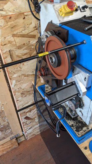
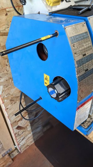
I cut a smaller hole in the back on the angled section for the 2 stepper motor cables and the encoder cable. This is what it looks like with the original studs installed and the cover installed:
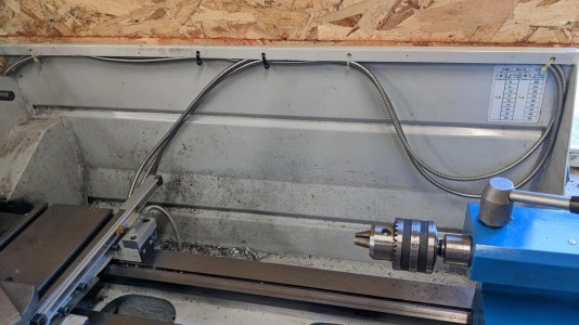
Performed some cable organization of the DRO cables; i like the loop for taking up the slack but time will tell if i like the mgmt on the back of the carriage. It's only a few zip ties to cut if i decide to change it but i need to run it for a while to see how well it works.
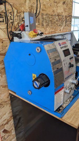
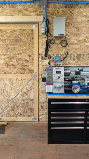
Here's a pic showing how the entire installation looks; i didn't want the stepper sticking out too far as there's a door right there. This is all done in a 14' x 28' shed - with about 14' x 14' with the lathe, mill, tooling, tools, and some other stuff. I wish i had more room, something more like a pole barn with a concrete floor but honestly this is super easy to heat with an electric heater and lets me tinker on stuff without too many compromises.
The ELS is working great. I hope those following along have enjoyed reading the progress updates.
I needed to cut a hole in the side cover so i figured i'd remove the studs in the headstock and replace them with longer rods, mark the stepper motor with grease then carefully slide the cover on the rods carefully lined up leave the grease imprint on the inside of the cover. Worked great. Cut the smallest hole i could and still have some room around the stepper. I suppose if you cut a square hole with a wiz wheel it could be a bit tighter but i think it has the perfect amount of clearance.


I cut a smaller hole in the back on the angled section for the 2 stepper motor cables and the encoder cable. This is what it looks like with the original studs installed and the cover installed:

Performed some cable organization of the DRO cables; i like the loop for taking up the slack but time will tell if i like the mgmt on the back of the carriage. It's only a few zip ties to cut if i decide to change it but i need to run it for a while to see how well it works.

Here's a pic showing how the entire installation looks; i didn't want the stepper sticking out too far as there's a door right there. This is all done in a 14' x 28' shed - with about 14' x 14' with the lathe, mill, tooling, tools, and some other stuff. I wish i had more room, something more like a pole barn with a concrete floor but honestly this is super easy to heat with an electric heater and lets me tinker on stuff without too many compromises.

The ELS is working great. I hope those following along have enjoyed reading the progress updates.


