Emco Compact 8 dimension request

Good to hear Tom, I thought I was losing my marbles on the calculations:<) Very close numbers to what I was getting too! That is why I left possible room for up to a 5.25" dia. primary driving pulley and leaning towards the V-belt idea:<) Thank for the compliment and more thanks for your measurement efforts my good man:clapping: Too fast too post , yes that would a great idea too!!! Not cut yet either:<)
 
I am leaving a rebuild guide pdf for you and others as well. They contain nice wealth of info for 9x20 ( also applies to Emco as well ). Someday, if there's demand I'll go create a thread containing many PDF documents related to 9x and 8x lathes.

Something important to note, the headstock only sits on shims and is above by 1 mm off of V-ways otherwise you cannot adjust the headstock.
 

Attachments

  • Rebuild Manual.pdf
    2.9 MB · Views: 13
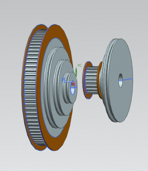
All right, been busy at the computer in my off time and finally have settled on the 2 drive pulleys at 1:4 ratio, 20 teeth and 80 teeth , 1.25 dia x 5.250 dia. which should give me 98-1720 rpm range! The belt is on order. Lots to do now, it may take a while, but I'm on it!
 

Attachments

  • Pulley Set-Up.png
    Pulley Set-Up.png
    90.3 KB · Views: 18
Nice pulleys but toothed pulleys are a pain in my ass to get aligned in my opinion and my lathe is out of service while I try fix it.
 
Thanks Fermic, I almost went with Micro-groove ribbed V-belts but I don't want any chance of slipping. Besides, I have a 5-Axis CNC at my disposal:<) Going to give it a whirl !
 
Steve:

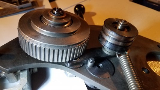
It looks like you're adding some material to the edges of the pulley to guide the belt. Normally a good idea, but be aware that the idler arm moves below that pulley and it may limit your available space.

See attached image. The rectangular idler arm is about 0.238 thick by 0.788 wide (+/-). The washer below the idler arm providing clearance from the plate is about 0.077 thick.

My pulley has only about 0.375 clearance from the back edge of the pulley to the adjacent support plate. The pulley itself appears to be mounted on 3/4 inch hex bar with turned sections to locate the shaft against the plate and provide the required pulley offset.

I understand you can adjust your pulley offsets to your desired setup, but you eventually have to get back to your driven spindle pulley. I thought you were using a thicker mounting plate. Probably best to look at those pulleys from a front or top view to see where you end up on the spindle.

Glad you're having fun cutting metal. No fun for me, I'm heading out to cut the grass.

TomKro
 

Attachments

  • EmcoC8DrivePlate_33resize.jpg
    EmcoC8DrivePlate_33resize.jpg
    1.4 MB · Views: 18
Awesome pic there,Thanks! I see your point Tom, and the shields are an afterthought and negotiable also. I guess as long it's straight, where is it going to go:<) I will leave that decision for after the mock up as you suggest! Edit....looks like I'm .325 as it stands now and I think I can shave another .05 with modifications:<) Excellent info!! ;)
 
Slight changes to the counterbore depth on the last pulley can also give you some position flexibility, so you may be able to keep your belt guides after all.

Since my machine is still in pieces, here's a few more pics that might help with those last few parts:


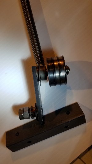
EmcoC8BeltTensionArm_resized.jpg

The swing arm for the belt tensioning lever has a pin to pin centerline distance of about 2-3/8 inch. The idler itself is about 1.82 OD, 1.020 long. Note that it is designed to float quite a bit along the pin. Both sides of the idler are counterbored a little less than an 1/8 inch deep to allow it to float with the various belt positions.


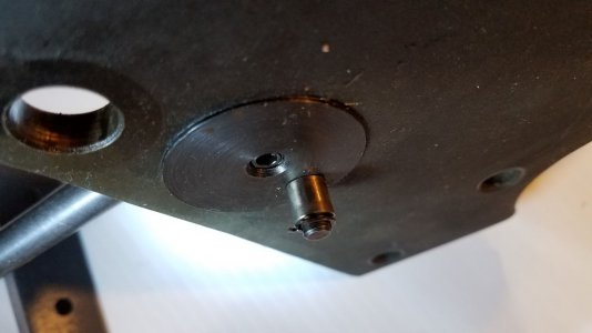
EmcoC8BeltTensionCam.jpg

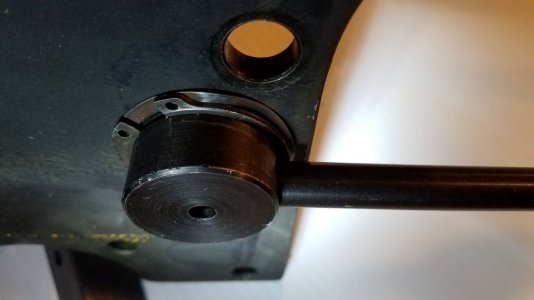
The cam that pushes on the idler arm is about 0.350 OD, 11/32 long. Looks like it rides on a 1/4 inch pin. The setscrew locks the handle screwed thru the hub on the other side. The 1/4 inch pin centerline is about a 1/2 inch off the setscrew centerline.


EmcoC8CamHub_OutsideView.jpg

I thought this snap ring and wave spring was pretty slick. Might be hard to find that particular spring and snap ring, but you can probably make an inverted cup/cap to serve the same purpose.

Hope the pics help.

TomKro
 
MORE AWESOME!! I couldn't save these pics fast enough!!! I was waffling about asking you for a few more pics, but you must have felt my vibes:<):<) Really helpful! What I did notice that on my exploded view that I found on line that I don't see that 90 degree , thick adjusting bracket anywhere? Does that adjust the tension from the motor to the drive pulley?

CHEERS!!
 
Back
Top