EMCO V13 - Brake Lock-up Problem?

cwilliamrose

H-M Supporter - Gold Member
H-M Supporter Gold Member
Joined
Jun 28, 2021
Messages
142
I was using the lathe today taking a skinny cut with a boring bar when the machine came to a grinding halt, literally. I stopped the motor, took it out of gear and the chuck spins freely. Trying to engage the motor, briefly, in either forward or reverse results in the motor straining to rotate and not getting very far. The brake seems to be engaged even when the motor gets voltage. At first I thought I may have lost a leg of our 3 phase service but the other machines run normally.

From this I'm assuming the contactors (C2 & C3) are OK and the shared leg (between forward and reverse) is the leg that operates the brake. I understand from reading another thread that the brake operates at 24 volts off of one leg. Is the 24V transformer inside the motor's connection box? Is it a common part I could source somewhere? Or, is it likely NOT the transformer that failed and I need to look elsewhere -- like the main contactor (C1)?? I have not yet looked for output from C1 because I'm not sure the motor would even try to turn without voltage from all three legs.

As you can see, I'm not a sparky-type so I'm here to find an expert or three to help guide my trouble shooting.
 
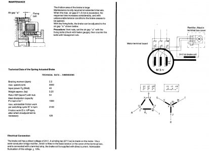
Seems like this is not being addressed, so maybe I can provide some info. The schematics vary quite a bit on this model lathe, the 24VAC transformer should be in the main control box, power then would go through a contactor/relay which would be activated when in the run mode. Power then goes to the motor brake unit. Within the braking unit there is a rectifier under the terminal cover which converts the AC to DC. One could remove the brake unit and check if there is continuity in the coil, and also if power is going to the coil in the leads that go to it. One would need to trace the wires back from the brake unit connections at the motor to see which contactor/relay is involved.

Also the brake wears and it is possible that it is out of adjustment and the release travel is not sufficient to disengage and requires adjustment per the manual.
Motor Brake.jpg
 
Thanks for the reply. I checked the power this morning and found good results on all three legs coming out of C1 (Main Contactor). There doesn't seem to be any high resistance contacts in C1, C2, or C3.

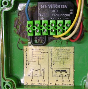
Below is the inside of the cover. Looks like the blue and red wires go directly to the coil and I could measure the coil's resistance there. If I get a good reading there then I would need to access the adjustments to the brake -- somehow. Given how suddenly this happened I wonder if the state of adjustment could be the cause. It was like a switch was thrown without any warning.........
Rectifier Under Cover.JPG

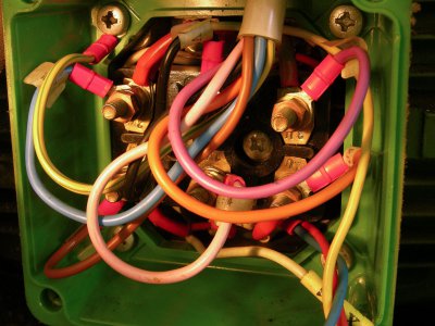
Motor Terminal Box.JPG
 
Last edited:
So two things I would check, connect an AC meter to the white and yellow wire going to the bridge rectifier and momentarily flip the motor on/off too see if you are getting ~24VAC to the bridge rectifier and/or try to measure 24VDC between the blue and black wire in the same scenario. You can attach some short wires to the screw terminals if needed for testing, just make sure they do not short. If the coil to the brake is good, and I would assume it is under 100 ohms and more like a few ohms, and you have 24VDC at the +/- terminals from the rectifier to the coil, then it needs to be adjusted. It is also possible that something is broken or something else. In cases where I do a VFD replacement on a brake motor I remove the brake unit from the back of the motor.
 
The coil is reading 15.4 ohms.

I'm getting ~23VAC from the yellow and white wires.

I'm getting only mV DC readings from the blue and red wires.

The rectifier gets warm in a hurry with me only having the power on for long enough to get the readings (1-2 secs at a time). Could not hold my finger on it for very long.

I believe the contacts are arcing when I engage the contactors using the switch. I used the button to manually make the contacts and didn't see any arcing.
 
It is unusual but it sounds like the rectifier has failed and is shorted. I have attached the specification information on the stock one you can get from eBay or you can buy one from an electronics house for less. Just note the orientation (they are both the same) when you install it, the two inner leads are AC the two outer are + ~~ -. The one below GBU1010 is $1.01 plus shipping (maybe get a spare) and is rated at 10A at 1000V, the stock one is 4A at 800V. Normally these are totally encased in plastic, but can be mounted to increase heat dissipation which is probably why yours failed. If there is a metal portion to the case it may need to be insulated if connected to one of the pins.


Added 20A version SMC Diode Solutions GBJ2010TB with similar pin out spacing as stock, cost is $1.35 maybe less shipping cost.
 

Attachments

  • SKB B 250.pdf
    66.8 KB · Views: 2
  • GBU1010.pdf
    278.6 KB · Views: 1
  • SMC Diode Solutions GBJ2010TB.pdf
    340.8 KB · Views: 1
Last edited:
Thanks! The parts are ordered.

If I put 24VDC to the blue and red wires the brake should release. Any reason I shouldn't do that? I'll be using an old HP lab power supply. I can use the machine while I wait for the parts and I could even rig up a temporary brake switch.......
 
Ye it should work if you remove the rectifier and connect positive to the red and negative to the blue. You may need 1-2A supply at 24 VDC.
 
I think I have 3 or 4 amps available from that power supply. And yes, I figured I'd pull the rectifier, it has to come out anyway. I'll look at that other part you added to the post above. Many thanks........Bill
 
Back
Top