- Joined
- Dec 17, 2021
- Messages
- 10
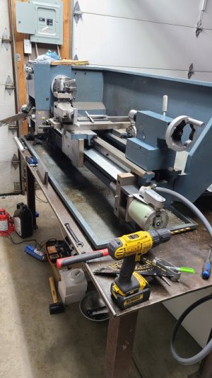
Alright, I figured I'd get into some lathe work. . . So I went and bought an ENCO 110-1351 that had its own home made CNC on it. Was sold to me as working order. Figured great, I'll get to start playing around!
NOPE. hahahaha. Which is all good. Massive learning curves are fun.
So, machine wouldn't talk to the computer at all. I figure I'll just build my own. Which went well up until spindle control!
Okay, to the root of the problem. I cannot find a wiring diagram so I am limited to what I can see in front of me and touch with a meter.
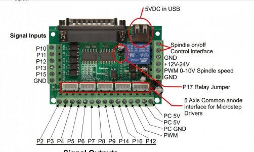
I have a cherry hall sensor on spindle, wired to a DB25 board. (Photo attached)
I wired:
GND - GND
Sensor - P10
Power - PWM 0-10 Spindle Speed
Now, inside the lathe is where I am a bit lost. I have to wire the motor in and wire in relays that take signal from the board to turn spindle on/off and reverse.
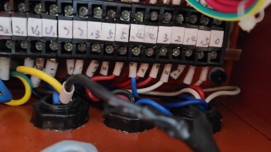
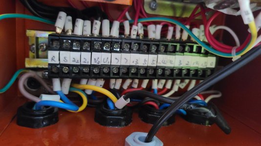
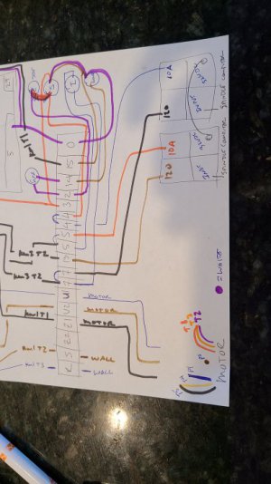
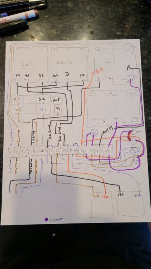
I have attached a nice grade 3 drawing of what I can see for wiring (haha sorry in advance).
The lines go as follow:
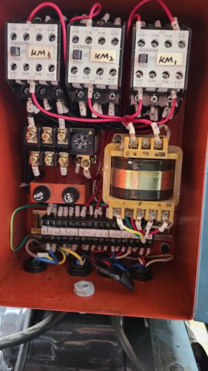
Blue to wall- R - km1 (T3)
Brown to wall - S - km1 (T2)
Z2
Black from motor- Z1 - km1 (T1)
Brown to motor - V2 - bottom left amp board -
top amp R2 - km3 (T1)/km2(T1)
Blue from motor- U1 - bottom right on amp board - S2 (top right amp board) - km3(T3)/km2(T3)
Blue wire from switches - 7 - paired - km3 (T2)
Black wire to relays - 7 - paired -
Brown wire to relays - 13 - km2(t2)
Blue from switches - 5 - paired - amp dial
Red wire to relay - 5 - paired -
Blue from relay - 4 - paired -
Red from switches - 4 - paired - jumped
Red from switches - 3 - km1 (t1)
White to switches - 2 - fuse- 14
From fuse - 14 - Brown into switches
Brown to switches - 15 - km1 (t1)
White from switches - 0 - pin labeled 5 on yellow thing and A2 on bottom of KM1
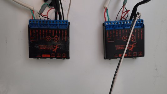
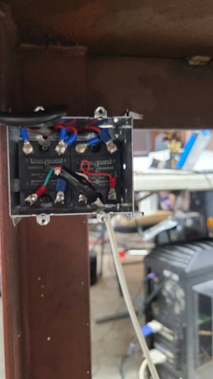
I then have the amp boards (gordos SSR 120 - 32s) (see photo)
Brown goes to top left (120) - red top right (10amp) (jumper to right side of second SSR)
Green wire spindle to input
Bottom right Red jumper to bottom right on second relay
Black to top left (120) Blue to top right (10amp)
White wire spindle to input
Jumper on bottom right to left side SSR
One of the wires in the lathe box is intercepted and run to the relays so that the computer can turn on/off the KM1 - KM3 (I don't know what they are... relays as well?)
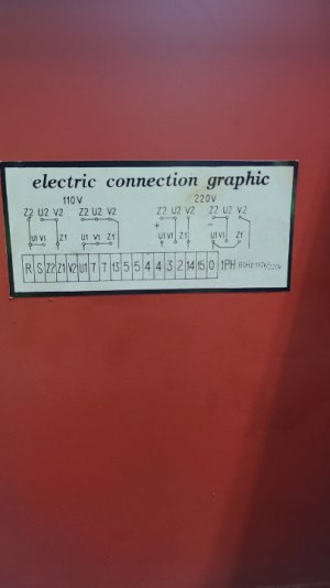
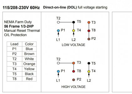
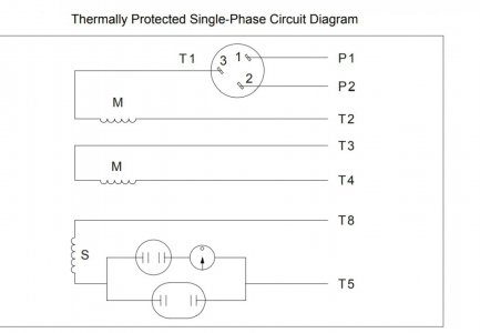
I attached the only wiring thing I could find for the ENCO and also the wiring diagrams with the motor.
Hopefully someone's got some insite into how to wire the motor to the lathe using the relays haha!
Thanks,
Kyle
NOPE. hahahaha. Which is all good. Massive learning curves are fun.
So, machine wouldn't talk to the computer at all. I figure I'll just build my own. Which went well up until spindle control!
Okay, to the root of the problem. I cannot find a wiring diagram so I am limited to what I can see in front of me and touch with a meter.
I have a cherry hall sensor on spindle, wired to a DB25 board. (Photo attached)
I wired:
GND - GND
Sensor - P10
Power - PWM 0-10 Spindle Speed
Now, inside the lathe is where I am a bit lost. I have to wire the motor in and wire in relays that take signal from the board to turn spindle on/off and reverse.
I have attached a nice grade 3 drawing of what I can see for wiring (haha sorry in advance).
The lines go as follow:
Blue to wall- R - km1 (T3)
Brown to wall - S - km1 (T2)
Z2
Black from motor- Z1 - km1 (T1)
Brown to motor - V2 - bottom left amp board -
top amp R2 - km3 (T1)/km2(T1)
Blue from motor- U1 - bottom right on amp board - S2 (top right amp board) - km3(T3)/km2(T3)
Blue wire from switches - 7 - paired - km3 (T2)
Black wire to relays - 7 - paired -
Brown wire to relays - 13 - km2(t2)
Blue from switches - 5 - paired - amp dial
Red wire to relay - 5 - paired -
Blue from relay - 4 - paired -
Red from switches - 4 - paired - jumped
Red from switches - 3 - km1 (t1)
White to switches - 2 - fuse- 14
From fuse - 14 - Brown into switches
Brown to switches - 15 - km1 (t1)
White from switches - 0 - pin labeled 5 on yellow thing and A2 on bottom of KM1
I then have the amp boards (gordos SSR 120 - 32s) (see photo)
Brown goes to top left (120) - red top right (10amp) (jumper to right side of second SSR)
Green wire spindle to input
Bottom right Red jumper to bottom right on second relay
Black to top left (120) Blue to top right (10amp)
White wire spindle to input
Jumper on bottom right to left side SSR
One of the wires in the lathe box is intercepted and run to the relays so that the computer can turn on/off the KM1 - KM3 (I don't know what they are... relays as well?)
I attached the only wiring thing I could find for the ENCO and also the wiring diagrams with the motor.
Hopefully someone's got some insite into how to wire the motor to the lathe using the relays haha!
Thanks,
Kyle
Attachments
-
 Screenshot_20211217-172718_Drive.jpg131 KB · Views: 11
 -
 20211217_092641.jpg61 KB · Views: 10
 -
 20211216_233307.jpg39.1 KB · Views: 9
 -
 20211217_091930.jpg53.1 KB · Views: 9
 -
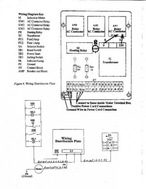 Diagram 1-page-001.jpg70.7 KB · Views: 7
 -
 Screenshot_20211215-184648_Drive.jpg75.5 KB · Views: 8
 -
 Screenshot_20211215-184702_Drive.jpg45.7 KB · Views: 7