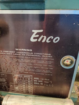
Enco 110-2031 Lathe, wiring setup

grhm

Registered
Registered
Joined
Jun 4, 2021
Messages
47
I have just acquired a lathe that claims to be an Enco 110-2031 manufactured in 1988 (/7), serial number 1000 (if you can believe it). It was apparently manufactured in Taiwan.
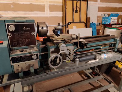
IMG_20210618_204207.jpgIMG_20210522_101459.jpg

I believe this lathe was setup for 110v operation, despite the large "220v" sticker on the outside of the wiring box, because it has a 5-20R cord attached (normal 110v cord with the sideways blade). While I had originally believed it was setup for 220v, this is ok for now, because I have these outlets available to me, while 220v is not yet installed.

I do not have a manual for this machine (would love a PDF copy if anyone had one!), so I am not confident of the wiring diagram. Also, there is a switch missing that I need to wire up (bottom of the machine, just to the right of the threading gearbox):
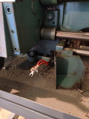
IMG_20210619_101335.jpg

These wires originate in the wiring box, marked here in red (the two marked in blue go to the e-stop switch):
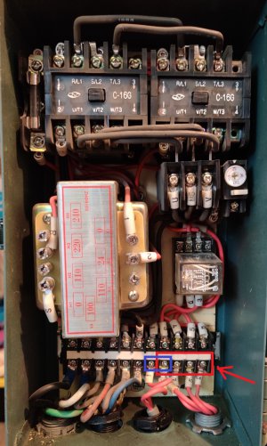
lathe_wiring.jpg

Can anyone help me out with what switch I'm missing and how I'd wire it up? Also, it'd be fantastic if anyone had a wiring diagram or could verify that my wiring looks correct. Thanks!
 
this thread may help, it has a very similar wiring diagram posted from before the retrofit

 
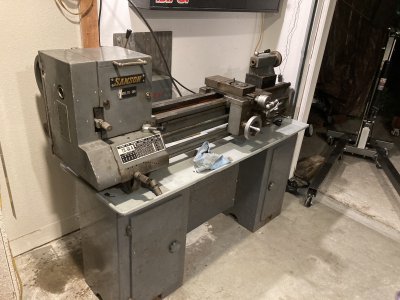
Looks very similar to the Samson (Tida) lathe I just bought.

IMG_9574.jpg

Definitely suggest becoming a supporting member here for access to the downloads section.


Then you can access manuals here:


Here's some history that may be of use.


John
 
your transformer is currently tapped for 220v operation- don't plug this lathe into 120v without tapping it for lower voltage
the 4 red wires (assuming3, 4,5,6) are for directional control
one or 2 wires may have constant power, the other 2 indirectly pull in the forward or reverse contactor respectively

it looks like the system is intact
you can test operation by assuring there's no wires making contact with the frame
isolate the (4 red wired assumed to be)3, 4, 5 ,6 wires so as they cannot touch each other or ground out against the frame
add some single phase 220/240 volts through the power cord
test voltage from 3 or 4 to ground, if you have voltage present, this is the control power- a pairing of other 2 wires determine direction
if you were so inclined, you could disconnect power from the machine and connect (the assumed pairing) wires 3 and 5 together, and plug the power cord in after making sure no feeds are engaged.
WARNING: if the system is functioning correctly, the spindle may rotate upon plugging the machine in - if not prevented from doing so by the emergency stop switch being activated !!!!
the e-stop is generally a maintained contact normally closed switch, that when activated, stops flow of control voltage and operation.
knowing this, you could use the E-stop to turn off and on the spindle for troubleshooting purposes
test the other 2 red wires for voltage to ground, if the spindle doesn't turn

there are 2 cam operated microswitches on my lathe for directional control from the apron switch, yours may have had a slightly different arrangement like a 3 position switch in the absence of an apron switch, but the idea would be the same.
a DPDT toggle switch, could be retrofitted to quickly restore operation
a Drum Switch could be retrofitted easily
a pendant station could be wired with 2 buttons for directional control
OEM parts may be available somewhere, but it may be difficult to find the actual control switch for your machine- a retrofit may be in order

(edited for better information)
 
Last edited:
Also, and this is important!!!!

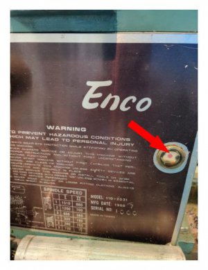
You need to put oil in for the spindle bearings before you run it or you will be sorry very soon. The oil fills on these machines are accessed by lifting the belt/gear cover on top of the machine.

IMG_20210522_101459-a.jpg

John
 
Last edited:
Another thought occurred to me,
be sure remove and to test the control fuse located on the left had contactor in the upper left of the control box
if this fuse is faulty, the system will not work
 
Here's some files for the 110-2033/2034 if it helps:
Mike spotted the transformer tap is set for 220 volts so it looks like that's how the machine is wired now
I recommend keeping it that way and run a new line
-M
 

Attachments

  • Enco-110-2033-&-2034-Manual.pdf
    1.7 MB · Views: 54
  • Enco-110-2033-&-2034-contactor-wiring.pdf
    111.5 KB · Views: 37
  • Enco-110-2033-&-2034-motor-wiring.pdf
    65.5 KB · Views: 31
Last edited:
Awesome! The switch ("apron switch"?) is completely missing; is there any hope I could get one, or one that would work? What would it be called?
 
You could try Grizzly, the G9249 may be a match.

Go on their website and see if it looks like the one you’re missing.

John
 
I'm not honestly sure what the parts I'm missing look like. The G9249 seems to simply have two microswitches actuated by an eccentric bracket; the eccentric bracket is available, but the bracket that holds the switches themselves is not. Does someone happen to have a picture of what I'm missing? I have a 3D-printer and am a not-totally-incapable CAD operator; perhaps I could work something up that would work.
 
Back
Top