- Joined
- Nov 23, 2014
- Messages
- 2,606
Back with another reproduction Erector set part. This one was part number “AZ” bull ring plate. First, the obligatory history lesson. . .
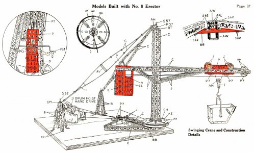
The A. C. Gilbert Company, based in New Haven, CT, bought the Noble Manufacturing Company in 1927 (also based in New Haven). Noble was known for an elaborate toy crane. Gilbert must have liked the toy and adapted some of the newly acquired parts directly into the Erector set toy line. Most of the parts were redesigned to save some bucks; the rotating base “variant” was done with new in 1927-part nos. “AY” bull ring and the “AZ” bull ring plate.
Noble Manufacturing Co. crane toy. Gilbert adapted (cheapened) a number of the intricate parts for use in Erector sets
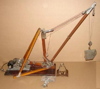
"AZ" bull ring plate (~4" diameter) was used as a base for a number of crane models
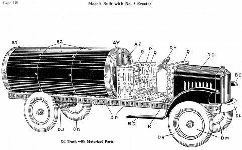
"AZ" was also used to close out the ends of a tanker truck model
Making reproduction Erector set parts is a VERY niche market! There are probably around 2000 collectors in the country with varying levels of “insanity”; some have hundreds of sets, others 1 or 2. Some parts may interest the whole 2000-collector market, others, maybe none. The Gilbert Company sold close to 50 million Erector sets through the years, so plenty of original common parts are out there. My challenge is picking an uncommon part that has a limited market (I don’t want to be stuck at the lathe/mill all day making the same thing) and can be made so it’s profitable.
Another call to reproduce something is because I need it. I’m not collecting them anymore, so not much call there! I still attend shows to bs with buddies I’ve made over the years and try to peddle some stuff. They aren’t all big successes! Here’s a link to a ‘P37’ collar I made that was a dud.

 www.hobby-machinist.com
I made some money on them, but at the ~$0.50 a piece sales price while making around 20/hour, I won’t be scheduling them into the “production schedule” anytime soon! Though I am a dirty, filthy capitalist, I don’t mind the occasional “loser” if I’m learning something new. That was the case for the P37 collars.
Which FINALLY brings us to the “AZ” bull ring plate. These parts in repro form (there was a now-deceased guy who made them years ago) sell for ~$10 each. World-wide market for them? Maybe 50 to 100 pieces tops.
First step was deciding on the basic construction technique: CNC the holes, slots and outer diameter or make a punch template and knock them in manually on my Roper Whitney 218 punch press; I went the CNC route. The upside of punching holes is no deburring is required (drilling holes/milling slots on the CNC does leave burrs in sheet metal). Downside is I’m tied to the press knocking in 16 holes and 8 slots per part. I went the CNC route as deburring with a Scotchbrite wheel only takes a minute; something I do while the next batch of parts is being drilled/milled on the Tormach.
Next step was devising a holding fixture for the blanks. I figured a 2-step process: First, drill/mill the holes and slots. Then a second set up to cut the square blank into a circle. I posted a POTD a while back on making a 0.650” diameter punch for my RW 218 press. That’s the hole size in the center of the “AZ”, holding fixture would have a slightly smaller center pin to locate the blank, and a screwed down clamp plate on top. I’d cut the blanks on my Tennsmith shear to size, then punch the center hole on the RW 218.
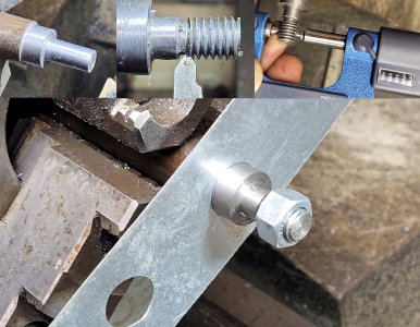
The pin was turned on the lathe and single-point threaded with a 3/8”-16 thread. The pin has a 3/8” shoulder for locating itself to the holding plate.
The holding fixture base plate and clamping plate were done on the Bridgeport. The locating pin was nutted to the base plate, the clamping plate secured on top pinning blanks that set over the center boss. I first ran the CNC routine to knock in the slots/holes in the fixture base plate and clamping plate. I knock the holes/slots all the way through the base fixture as the “nubs” from drilling (the “cymbal” left when the drill bit goes through the sheet metal) need to go somewhere. The through holes let the “nubs” fall through the bottom of the fixture. I learned from past mistakes when not giving them a place to go; they ended up on the lower plate surface after pulling a blank and/or stayed in the drilled hole in the blank.
Centering pin turned on the lathe; will be used to locate a blank to the CNC holding fixture
Holding fixture: Blank (real part shown here) sets over the pin in the center. A plate is then screwed down on top to hold the blank in place.
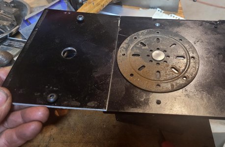
Ran the routine through the top clamp plate and base. Original part set in place after the fact as a "sense check".
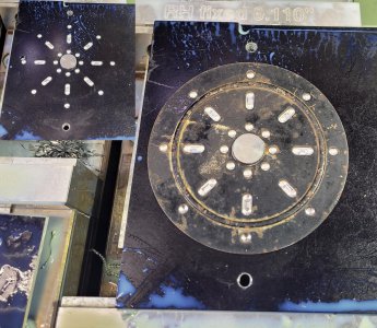
Started with single blanks, then went to stacks of 3
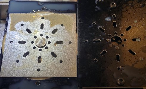
I proved out the routine running individual blanks, then went to stacks of 3. As an aside, my first routine took 5 minutes to drill the holes and mill the slots. The original routine drilled the small ring of holes, the end points of the slots, and the outer ring of holes. Then swapped in an 11/64” end mill to complete the slots. I changed the order to drilling the 4 holes in line on each leg to knock off some of the table movement; got the routine down to 3 ½ minutes.
Now that the holes/slots were in, time to cut the square blank to a disk. Plan here was to use the same fixture base plate and screw a stack of parts down using 4 of the outer holes as locators. A piece of 1/8” aluminum would set on top as a clamping plate. The outer holes are at 0, 45, 90, 135, etc. degrees. I did the trig to drill and tap four 8-32 mounting holes at 22.5, 112.5, 202.5 and 292.5 degrees. Set a stack of 3 blanks over the center boss/pin, clock them 22.5 degrees, set the clamping plate on top and screw the stack in place. Hit “CYCLE START” and 75 seconds later had 3 trimmed parts.
The base fixture has tapped holes for clamping the blank(s) down with a second aluminum plate. The routine cuts the square blank into a disk.
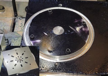
There were two versions of this part. No idea why they made the “engineering change” in 1928; but a circular embossment was added that year. The embossment is ~0.125” wide and ~0.025” deep. My only thought was for stiffness, though the flat part in 0.036” stock is still pretty stiff.
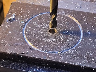
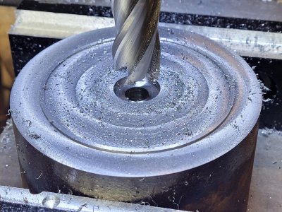
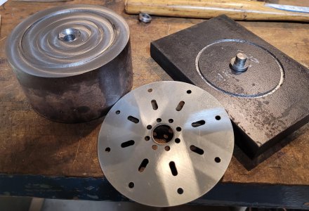
I made a “mash” die set to add the embossment; nothing special about the material used, just stock on hand. The bottom die has a 0.125” groove cut ~0.060” deep. I did that on my Bridgeport which has an Anilam (circa 1981) 2-axis CNC. The top die was made from a 4” round. This one had everything but a 0.050” wide ring ~0.030” tall embossment cut away. A pin to locate the blank between the dies was turned on the lathe. Process was to mash the 0.036” thick part between the two dies with a 20-ton press. I made up 36 of them and see a little wear on the die with the raised ring as the stock was plain carbon steel, not tool steel. If I needed to make a couple hundred of them, I could try case hardening the existing die. Or, pick up a 4” round of O1 and make a hardened die. Plan “A” moving forward is to recut the existing soft die as the CNC routine makes the cuts in about 5 minutes.
One die for putting an embossment ring into the part. Drilling out a centering pin hole here.
CNC'd away at the surface leaving a raised area that nests into the groove of the die half above. Cutting a clearance hole for the centering pin.
Die halves and a blank
Set a blank over the centering pin, set the die halves together and mash away on a 20-ton press
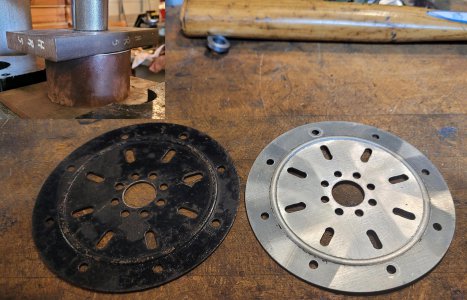
Few hours work
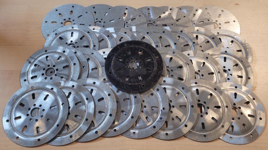
The originals were painted black, time for a trip for some primer and paint. Wish me luck on eBay and at shows!
Thanks for looking, Bruce
The A. C. Gilbert Company, based in New Haven, CT, bought the Noble Manufacturing Company in 1927 (also based in New Haven). Noble was known for an elaborate toy crane. Gilbert must have liked the toy and adapted some of the newly acquired parts directly into the Erector set toy line. Most of the parts were redesigned to save some bucks; the rotating base “variant” was done with new in 1927-part nos. “AY” bull ring and the “AZ” bull ring plate.
Noble Manufacturing Co. crane toy. Gilbert adapted (cheapened) a number of the intricate parts for use in Erector sets

"AZ" bull ring plate (~4" diameter) was used as a base for a number of crane models

"AZ" was also used to close out the ends of a tanker truck model

Making reproduction Erector set parts is a VERY niche market! There are probably around 2000 collectors in the country with varying levels of “insanity”; some have hundreds of sets, others 1 or 2. Some parts may interest the whole 2000-collector market, others, maybe none. The Gilbert Company sold close to 50 million Erector sets through the years, so plenty of original common parts are out there. My challenge is picking an uncommon part that has a limited market (I don’t want to be stuck at the lathe/mill all day making the same thing) and can be made so it’s profitable.
Another call to reproduce something is because I need it. I’m not collecting them anymore, so not much call there! I still attend shows to bs with buddies I’ve made over the years and try to peddle some stuff. They aren’t all big successes! Here’s a link to a ‘P37’ collar I made that was a dud.

2017 POTD Thread Archive
Tonight I was just experimenting, trying to see if I could get a good shot of a MIG arc. I was using some shade 11 glass, and a 7 year old Nikon super zoom, as I'm not risking my good camera. Tomorrow I'm going to look and see if i can find any lighter glass locally.
 www.hobby-machinist.com
I made some money on them, but at the ~$0.50 a piece sales price while making around 20/hour, I won’t be scheduling them into the “production schedule” anytime soon! Though I am a dirty, filthy capitalist, I don’t mind the occasional “loser” if I’m learning something new. That was the case for the P37 collars.
Which FINALLY brings us to the “AZ” bull ring plate. These parts in repro form (there was a now-deceased guy who made them years ago) sell for ~$10 each. World-wide market for them? Maybe 50 to 100 pieces tops.
First step was deciding on the basic construction technique: CNC the holes, slots and outer diameter or make a punch template and knock them in manually on my Roper Whitney 218 punch press; I went the CNC route. The upside of punching holes is no deburring is required (drilling holes/milling slots on the CNC does leave burrs in sheet metal). Downside is I’m tied to the press knocking in 16 holes and 8 slots per part. I went the CNC route as deburring with a Scotchbrite wheel only takes a minute; something I do while the next batch of parts is being drilled/milled on the Tormach.
Next step was devising a holding fixture for the blanks. I figured a 2-step process: First, drill/mill the holes and slots. Then a second set up to cut the square blank into a circle. I posted a POTD a while back on making a 0.650” diameter punch for my RW 218 press. That’s the hole size in the center of the “AZ”, holding fixture would have a slightly smaller center pin to locate the blank, and a screwed down clamp plate on top. I’d cut the blanks on my Tennsmith shear to size, then punch the center hole on the RW 218.
The pin was turned on the lathe and single-point threaded with a 3/8”-16 thread. The pin has a 3/8” shoulder for locating itself to the holding plate.
The holding fixture base plate and clamping plate were done on the Bridgeport. The locating pin was nutted to the base plate, the clamping plate secured on top pinning blanks that set over the center boss. I first ran the CNC routine to knock in the slots/holes in the fixture base plate and clamping plate. I knock the holes/slots all the way through the base fixture as the “nubs” from drilling (the “cymbal” left when the drill bit goes through the sheet metal) need to go somewhere. The through holes let the “nubs” fall through the bottom of the fixture. I learned from past mistakes when not giving them a place to go; they ended up on the lower plate surface after pulling a blank and/or stayed in the drilled hole in the blank.
Centering pin turned on the lathe; will be used to locate a blank to the CNC holding fixture

Holding fixture: Blank (real part shown here) sets over the pin in the center. A plate is then screwed down on top to hold the blank in place.

Ran the routine through the top clamp plate and base. Original part set in place after the fact as a "sense check".

Started with single blanks, then went to stacks of 3

I proved out the routine running individual blanks, then went to stacks of 3. As an aside, my first routine took 5 minutes to drill the holes and mill the slots. The original routine drilled the small ring of holes, the end points of the slots, and the outer ring of holes. Then swapped in an 11/64” end mill to complete the slots. I changed the order to drilling the 4 holes in line on each leg to knock off some of the table movement; got the routine down to 3 ½ minutes.
Now that the holes/slots were in, time to cut the square blank to a disk. Plan here was to use the same fixture base plate and screw a stack of parts down using 4 of the outer holes as locators. A piece of 1/8” aluminum would set on top as a clamping plate. The outer holes are at 0, 45, 90, 135, etc. degrees. I did the trig to drill and tap four 8-32 mounting holes at 22.5, 112.5, 202.5 and 292.5 degrees. Set a stack of 3 blanks over the center boss/pin, clock them 22.5 degrees, set the clamping plate on top and screw the stack in place. Hit “CYCLE START” and 75 seconds later had 3 trimmed parts.
The base fixture has tapped holes for clamping the blank(s) down with a second aluminum plate. The routine cuts the square blank into a disk.

There were two versions of this part. No idea why they made the “engineering change” in 1928; but a circular embossment was added that year. The embossment is ~0.125” wide and ~0.025” deep. My only thought was for stiffness, though the flat part in 0.036” stock is still pretty stiff.
I made a “mash” die set to add the embossment; nothing special about the material used, just stock on hand. The bottom die has a 0.125” groove cut ~0.060” deep. I did that on my Bridgeport which has an Anilam (circa 1981) 2-axis CNC. The top die was made from a 4” round. This one had everything but a 0.050” wide ring ~0.030” tall embossment cut away. A pin to locate the blank between the dies was turned on the lathe. Process was to mash the 0.036” thick part between the two dies with a 20-ton press. I made up 36 of them and see a little wear on the die with the raised ring as the stock was plain carbon steel, not tool steel. If I needed to make a couple hundred of them, I could try case hardening the existing die. Or, pick up a 4” round of O1 and make a hardened die. Plan “A” moving forward is to recut the existing soft die as the CNC routine makes the cuts in about 5 minutes.
One die for putting an embossment ring into the part. Drilling out a centering pin hole here.

CNC'd away at the surface leaving a raised area that nests into the groove of the die half above. Cutting a clearance hole for the centering pin.

Die halves and a blank

Set a blank over the centering pin, set the die halves together and mash away on a 20-ton press

Few hours work

The originals were painted black, time for a trip for some primer and paint. Wish me luck on eBay and at shows!
Thanks for looking, Bruce

