- Joined
- Nov 23, 2014
- Messages
- 2,606
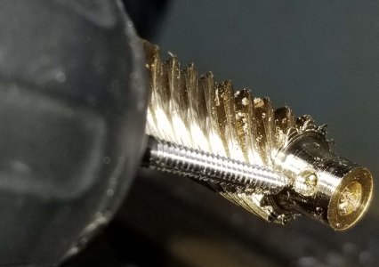
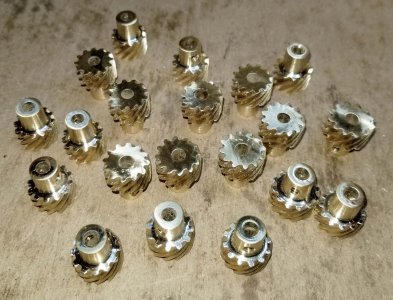
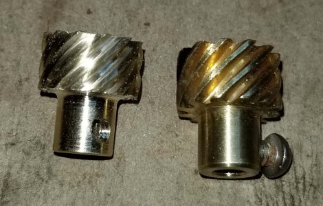
Here’s another Erector set reproduction part string. This one is for part number ‘FL’ helical gear. I shot lots of photos so probably a couple of posts in this thread for the whole story. First the obligatory history lesson. . .
Gilbert introduced a number of parts to demonstrate different types of motion (like step pulley drive, cams, eccentrics, universal joints, etc.) in 1929. These parts were included in just two sets, the 1929 No. 9 and the 1929 No. 10 sets. The A.C. Gilbert Company had acquired the American Meccano Company in 1928 which I suspect lead to the addition of the drive train parts. The Meccano building system was far superior to Gilbert’s toy with many more gears, pulleys and other special parts. The Meccano sets came with a manual that specifically showed different types of motion and mechanisms (like miter gears, eccentric cranks, etc.). It was marketed as “Engineering for Boys”. My belief is Gilbert recognized that the Meccano sets were superior in this regard, so they added a similar set of what were called “Mechanical Wonders” demonstrations of motion and mechanisms in the larger sets.
OK, on to the ‘FL’ helical gear. I scanned the manual a couple of times and can find only ONE model that used these gears. I find it curious that the only model page showing the ‘FL’ helical gears (as labeled in the back of the manual in the separate parts pages with prices for additional parts) has them mislabeled as part number ‘FW’ (which was actually a slotted crank). In the grand scheme of things, it was just a kid’s toy. . .
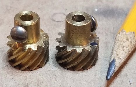
Couple of original "FL" helical gears.
Only page I could find in the manual using the gears
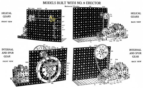
Being a part sold in just the two largest sets from 1929 – 1932 makes this a fairly esoteric part. So why bother with something that has a world-wide demand of maybe 30 pieces? I’ve never cut a helical gear before and wanted to take a crack at making them.
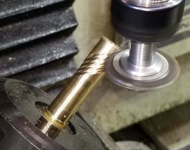
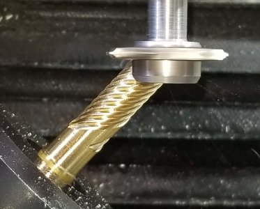
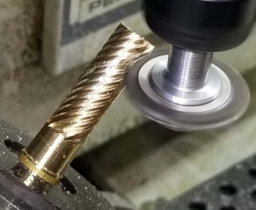
Helical gears are typically made on a universal mill. Nope, don’t have one but I do have a 3-axis CNC mill with a 4th axis rotary table. The ‘FL’ gears meet at a 90-degree angle to each other, the gear’s teeth are cut on a 45-degree angle to their axis.
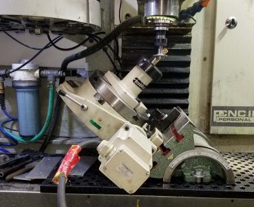
My plan was to mount the 4th axis on a 45-degree angle and hold the gear blanks in a 5C collet mounted to the 4th axis. The involute cutter would be held in an arbor in the spindle. Cutting motion along the blank would need to be on the X & Z axis with both moving at the same rate. On top of that, the 4th axis would need to rotate as the X/Z moved.
First step was to come up with a way to mount the 4th axis on a 45-degree angle. Yeah, wish I had Tormach’s Super Spacer with a tilting head at this point. I have a rotary table designed to mount either horizontally or vertically. My solution was to mount the rotary table on a 7” x 10” tilting table.
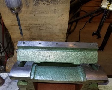
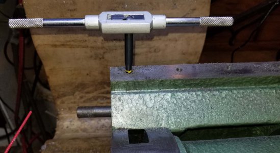
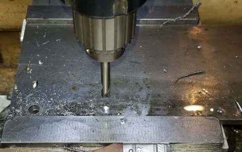
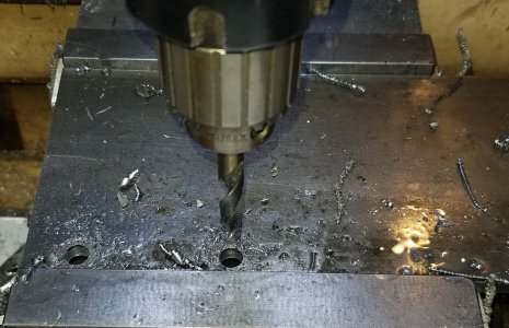
I ended up mounting a backstop to the tilting table to help locate the RT. Went to the Bridgeport and spotted, tap drilled and tapped holes for a backer plate. Then spotted and drilled holes in a piece of 4” x 10” x ¼” thick steel for the back stop. Bolted on the backstop and dry fitted the 4th axis on the bench. Held the 4th to the table with a couple of strap clamps.
Spotting, drilling tap holes and tapping the 7" x 10" tilting table
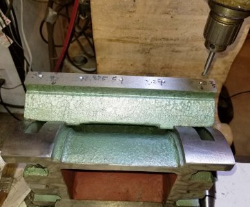
Spotting and drilling clearance holes in the backstop for the tilting table
Bolted the backstop to the table.
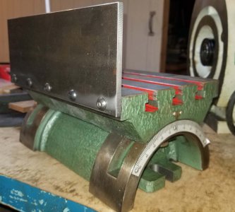
Mounted the 4th axis on the tilting table with a couple of strap clamps
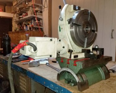
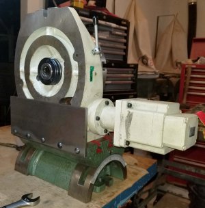
Mounted a 5C collet chuck to the 4th axis for holding the gear blanks
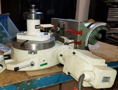
Moved the assembly to the Tormach and trammed in the backstop. Then tilted the table to a 45. Checked the angle with a protractor and fine adjusted with shim stock between the fixture plate and tilting table.
Swept the face of the backstop and adjusted the table for parallel to the Y-axis.
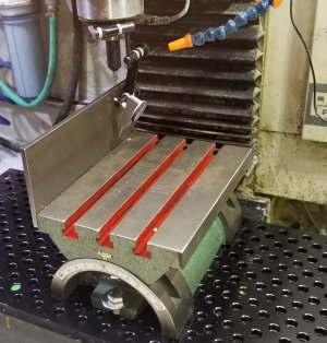
Mounted the 4th axis and verified tram of the table surface in the Y and Z.
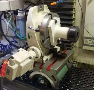
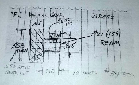
I have a few original ‘FL’ gears and a sketch of the dimensions. I consulted Machinery’s Handbook for the helical gear formulas which left my head swimming. As you can tell from my write up and methodology, I’m not a trained machinist. My dad was a shop teacher, but he didn’t spend much time in the shop with me. I had 4 or 5 shop classes in Junior High, experience and making mistakes has been my best teacher (and within the last 5 years some YouTube videos). Plus seeing how other guys do stuff on this forum! I figured why not forget the formulas and reverse engineer the set up.
The first hurdle was aligning the involute cutter to the center axis of the rotary table. I made an arbor out of ½” steel (diameter doesn’t matter) and turned a 90-degree point on the end. Plan was to mount the arbor on the 4th axis. I’d get the Y axis centered up by touching off on either side of the arbor and moving half-way in between. Get Z-height by eyeballing the center of the gear cutter to the point on the arbor. Get the X-axis by bringing the cutter up to the arbor’s point and jog until I pinned a piece of paper. Then X was adjusted by the radius of the cutter so the center of the cutter was on the center axis of the 4th axis. Zero’d out both X and Z at this point. All of the program moves would need to be coordinated between X and Z.
Turned a set-up arbor on the lathe to find the center of the 4th axis
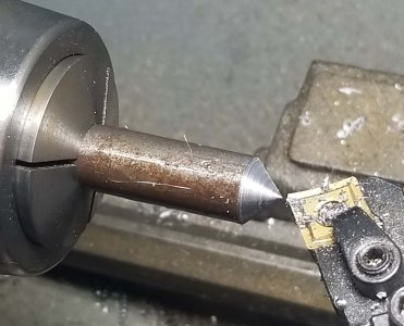
Found Y by touching off on either side of the arbor
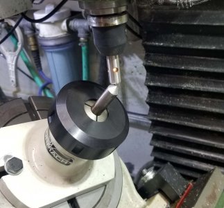
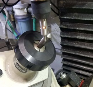
Found Z and X by eye and paper. Jogged the Z until the center of the cutter was centered on the tip of the arbor. Then jogged X until it pinned a piece of paper
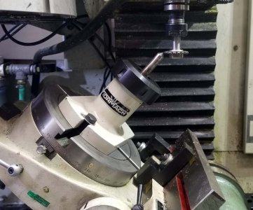
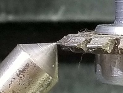
Moved off in the Y and moved the X the radius of the cutter as the center of the cutter, not the tip, should be on the center of the 4th's axis. Jogged X & Z equal amounts to as close to the 5C collet chuck nut as I was comfortable with, then zero'd both X and Z. Cutting motion would be on a 45 as X & Z would move together. These axis were zero'd at the low point, involute cutter would start in space above the gear blank.
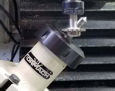
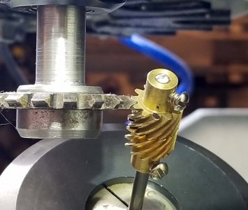
Next was figuring out how much the A-axis (4th axis rotary table) needed to rotate as the X and Z were moved along the gear blank. I mounted a pair of FL gears on an arbor and aligned them to each other. This made for a gear face about 5/8” long, figured the bigger the gear face, the better the measurement would be. I brought the X and Z down and adjusted the Y and A axes until the gear cutter was centered in the gear. Zero’d out the A-axis and noted the X/Z position.
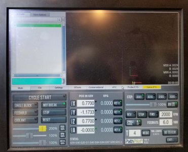
Moved X & Z together near the top of the existing gears. Jogged the Y and A axis until the cutter appeared to be centered in the gear. Zero'd the A-axis at this point and noted the X/Z coordinates
Marked a gear helix with a Sharpie so I was tracking just one tooth
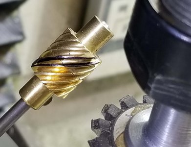
Then backed off the Y-axis and jogged X and Z down to the bottom of the gear. I’d marked one tooth of the gear with a Sharpie; rotated the A-axis and jogged Y until the gear cutter was centered in the gear. Noted the A-axis move relative to the X/Z move (X/Z moved from 0.770” to 0.448” while the A-axis rotated 100 degrees).
Moved down the gear with like moves in the X & Z to near the bottom. Rotated the A to an even 100 degrees as it was close to the bottom. Then jogged X, Y and Z until the cutter appeared to be centered on the same tooth.
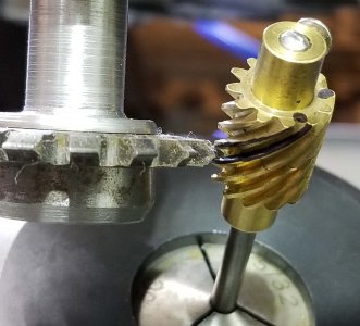
Noted that the A-axis rotated 100 degrees with X & Z moves from 0.770" to 0.448". Plan was to start the X & Z at 1.5"; math worked out to an A-axis rotation of 465.8 degrees over that move in X/Z.
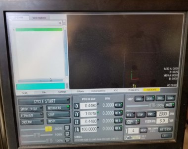
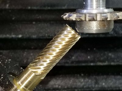
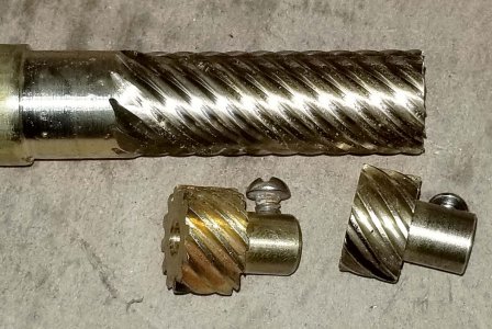
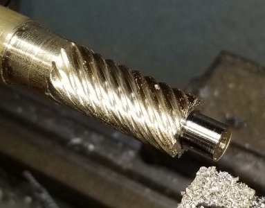
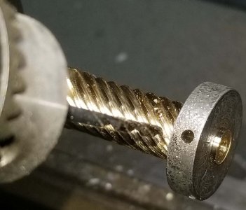
I figured on cutting about 1.5” of helical at a time which would give me two gears. Did the math which told me a move of 1.500” in the X & Z would require a 465.8-degree angle move on the A-axis. I measured the depth of cut in the existing ‘FL’ gear at around 0.070”.
Nearing the photo limit, so on to part 2. . .
Bruce
Gilbert introduced a number of parts to demonstrate different types of motion (like step pulley drive, cams, eccentrics, universal joints, etc.) in 1929. These parts were included in just two sets, the 1929 No. 9 and the 1929 No. 10 sets. The A.C. Gilbert Company had acquired the American Meccano Company in 1928 which I suspect lead to the addition of the drive train parts. The Meccano building system was far superior to Gilbert’s toy with many more gears, pulleys and other special parts. The Meccano sets came with a manual that specifically showed different types of motion and mechanisms (like miter gears, eccentric cranks, etc.). It was marketed as “Engineering for Boys”. My belief is Gilbert recognized that the Meccano sets were superior in this regard, so they added a similar set of what were called “Mechanical Wonders” demonstrations of motion and mechanisms in the larger sets.
OK, on to the ‘FL’ helical gear. I scanned the manual a couple of times and can find only ONE model that used these gears. I find it curious that the only model page showing the ‘FL’ helical gears (as labeled in the back of the manual in the separate parts pages with prices for additional parts) has them mislabeled as part number ‘FW’ (which was actually a slotted crank). In the grand scheme of things, it was just a kid’s toy. . .
Couple of original "FL" helical gears.


Only page I could find in the manual using the gears

Being a part sold in just the two largest sets from 1929 – 1932 makes this a fairly esoteric part. So why bother with something that has a world-wide demand of maybe 30 pieces? I’ve never cut a helical gear before and wanted to take a crack at making them.
Helical gears are typically made on a universal mill. Nope, don’t have one but I do have a 3-axis CNC mill with a 4th axis rotary table. The ‘FL’ gears meet at a 90-degree angle to each other, the gear’s teeth are cut on a 45-degree angle to their axis.
My plan was to mount the 4th axis on a 45-degree angle and hold the gear blanks in a 5C collet mounted to the 4th axis. The involute cutter would be held in an arbor in the spindle. Cutting motion along the blank would need to be on the X & Z axis with both moving at the same rate. On top of that, the 4th axis would need to rotate as the X/Z moved.
First step was to come up with a way to mount the 4th axis on a 45-degree angle. Yeah, wish I had Tormach’s Super Spacer with a tilting head at this point. I have a rotary table designed to mount either horizontally or vertically. My solution was to mount the rotary table on a 7” x 10” tilting table.
I ended up mounting a backstop to the tilting table to help locate the RT. Went to the Bridgeport and spotted, tap drilled and tapped holes for a backer plate. Then spotted and drilled holes in a piece of 4” x 10” x ¼” thick steel for the back stop. Bolted on the backstop and dry fitted the 4th axis on the bench. Held the 4th to the table with a couple of strap clamps.
Spotting, drilling tap holes and tapping the 7" x 10" tilting table


Spotting and drilling clearance holes in the backstop for the tilting table


Bolted the backstop to the table.

Mounted the 4th axis on the tilting table with a couple of strap clamps


Mounted a 5C collet chuck to the 4th axis for holding the gear blanks

Moved the assembly to the Tormach and trammed in the backstop. Then tilted the table to a 45. Checked the angle with a protractor and fine adjusted with shim stock between the fixture plate and tilting table.
Swept the face of the backstop and adjusted the table for parallel to the Y-axis.

Mounted the 4th axis and verified tram of the table surface in the Y and Z.

I have a few original ‘FL’ gears and a sketch of the dimensions. I consulted Machinery’s Handbook for the helical gear formulas which left my head swimming. As you can tell from my write up and methodology, I’m not a trained machinist. My dad was a shop teacher, but he didn’t spend much time in the shop with me. I had 4 or 5 shop classes in Junior High, experience and making mistakes has been my best teacher (and within the last 5 years some YouTube videos). Plus seeing how other guys do stuff on this forum! I figured why not forget the formulas and reverse engineer the set up.
The first hurdle was aligning the involute cutter to the center axis of the rotary table. I made an arbor out of ½” steel (diameter doesn’t matter) and turned a 90-degree point on the end. Plan was to mount the arbor on the 4th axis. I’d get the Y axis centered up by touching off on either side of the arbor and moving half-way in between. Get Z-height by eyeballing the center of the gear cutter to the point on the arbor. Get the X-axis by bringing the cutter up to the arbor’s point and jog until I pinned a piece of paper. Then X was adjusted by the radius of the cutter so the center of the cutter was on the center axis of the 4th axis. Zero’d out both X and Z at this point. All of the program moves would need to be coordinated between X and Z.
Turned a set-up arbor on the lathe to find the center of the 4th axis

Found Y by touching off on either side of the arbor


Found Z and X by eye and paper. Jogged the Z until the center of the cutter was centered on the tip of the arbor. Then jogged X until it pinned a piece of paper


Moved off in the Y and moved the X the radius of the cutter as the center of the cutter, not the tip, should be on the center of the 4th's axis. Jogged X & Z equal amounts to as close to the 5C collet chuck nut as I was comfortable with, then zero'd both X and Z. Cutting motion would be on a 45 as X & Z would move together. These axis were zero'd at the low point, involute cutter would start in space above the gear blank.

Next was figuring out how much the A-axis (4th axis rotary table) needed to rotate as the X and Z were moved along the gear blank. I mounted a pair of FL gears on an arbor and aligned them to each other. This made for a gear face about 5/8” long, figured the bigger the gear face, the better the measurement would be. I brought the X and Z down and adjusted the Y and A axes until the gear cutter was centered in the gear. Zero’d out the A-axis and noted the X/Z position.
Moved X & Z together near the top of the existing gears. Jogged the Y and A axis until the cutter appeared to be centered in the gear. Zero'd the A-axis at this point and noted the X/Z coordinates

Marked a gear helix with a Sharpie so I was tracking just one tooth

Then backed off the Y-axis and jogged X and Z down to the bottom of the gear. I’d marked one tooth of the gear with a Sharpie; rotated the A-axis and jogged Y until the gear cutter was centered in the gear. Noted the A-axis move relative to the X/Z move (X/Z moved from 0.770” to 0.448” while the A-axis rotated 100 degrees).
Moved down the gear with like moves in the X & Z to near the bottom. Rotated the A to an even 100 degrees as it was close to the bottom. Then jogged X, Y and Z until the cutter appeared to be centered on the same tooth.

Noted that the A-axis rotated 100 degrees with X & Z moves from 0.770" to 0.448". Plan was to start the X & Z at 1.5"; math worked out to an A-axis rotation of 465.8 degrees over that move in X/Z.


I figured on cutting about 1.5” of helical at a time which would give me two gears. Did the math which told me a move of 1.500” in the X & Z would require a 465.8-degree angle move on the A-axis. I measured the depth of cut in the existing ‘FL’ gear at around 0.070”.
Nearing the photo limit, so on to part 2. . .
Bruce
Last edited:


