- Joined
- Nov 23, 2014
- Messages
- 2,606
Here’s another Erector set reproduction part string. This one is for part number ‘HG’ zeppelin nose cone(s). First the obligatory history lesson. . .
Germany’s Graf Zeppelin was all the rage as the large airship started a world tour in 1928. The A.C. Gilbert Company took advantage of the fervor by creating a toy copy of the Zeppelin in 1929. The 5’ long model was built from a super-structure of common and modified parts. A number of specific to the Zeppelin parts were introduced also.
Gilbert had introduced the boiler (cylindrical tube of steel) and boiler top in 1924. The boiler top was a steel cone that set on top of the boiler tube. The boiler top was modified to become the nose cone of the zeppelin model and was numbered part number “HG”.
Standard Erector set part number "U" boiler top
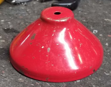
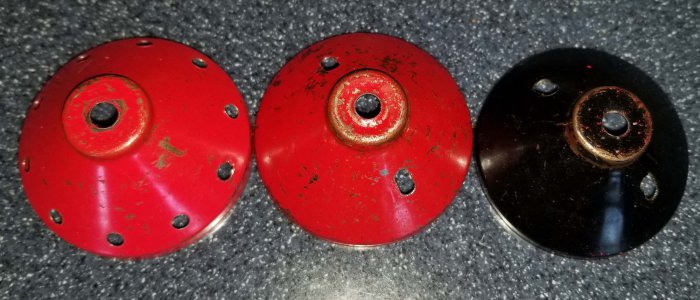
The original design used in 1929-30 sandwiched girders between two HG’s, a red-painted one on the outside and a black painted one on the inside. Two slots were cut into the parts for a pair of screws to hold the assembly together. The boiler top had a 5/32” hole through the center to accept a common axle rod. The zeppelin model was supported with a ¼” steel rod through the nose cone for display, so this hole was opened up to a little over ¼”.
1929/30 two-piece design
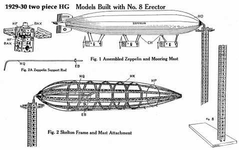
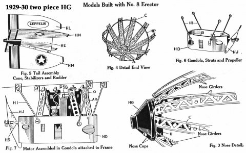
I suspect multiple hands were needed to tuck the ends of ten girders and the cloth bag between the two halves of the nose cone(s), then tighten the two screws. Gilbert simplified the design in 1931 with a one-piece nose cone with ten holes around the cone.
1931-32 one-piece design
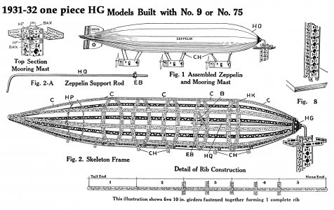
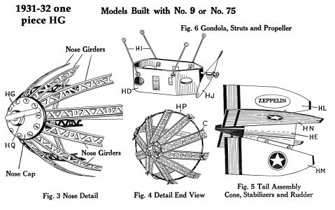
Being a bit of a dirty filthy capitalist, I track auctions for these parts on eBay and maybe take them on if prices are favorable. Well, one of my old (?) reproductions showed up on eBay recently and sold for $56! I remember making up a dozen or so of them 10 or 15 years ago and selling them for around $15, so time to make some more! Naturally, getting to a $56 bid requires someone else to bid $55, and there’s no guarantee the two guys will battle it out again and get the price higher than it should be. Regardless, gave me a reason to get into the shop.
Don't know if this was one I made up a few years ago or not, but at $56 they're worth doing again. . .

I made these before by cutting a paper pattern that was glued to a boiler top, center punched the holes, then drilled the top. It worked OK and was a pretty quick set up. I took a lot different approach this time.
I have a Tormach 1100 with a 4th axis rotary table. Plan was to mount the 4th axis on an angle plate at a 45 and run a routine to pop in the hole(s) or slots while indexing the nose cone to each hole/slot. Sure, why use a 2-minute set up with a paper pattern when I can go the way overkill route!
Started by making an arbor to hold the nose cone. Chucked up a piece of UHMW PE and turned a shoulder to 1” diameter. This would go into a 1” 5C collet on the 4th axis. Flipped the PE, faced, center drilled, tap drilled and tapped a hole for an 8-32 screw to fasten the boiler top to the arbor. Then turned the taper on the arbor to fit the boiler top.
Started by turning a 1" shoulder on a 2" round for mounting in a 5C collet. Flipped in a collet, then faced, center drilled, tap drilled, tapped.
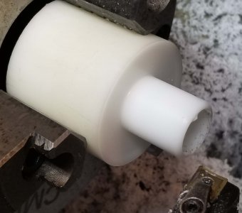
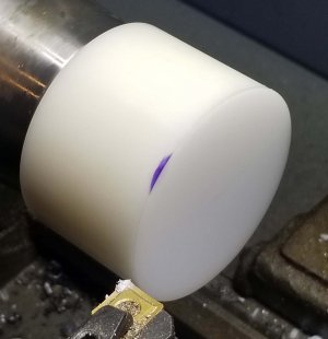
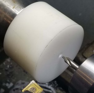
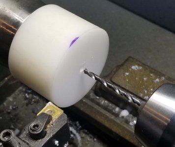
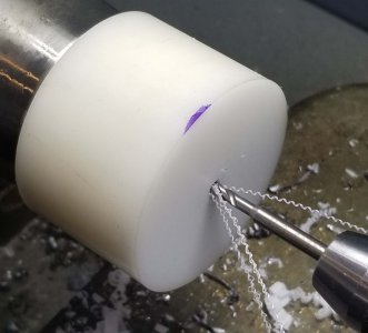
Gave my right hand a good work out on the compound to cut the taper
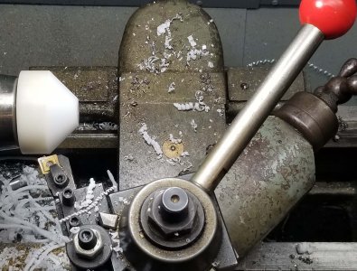
Final arbor with a boiler top in place
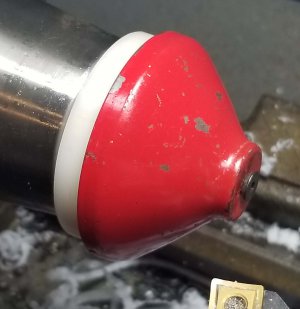
I figured as long as I had my crazy set up on the fixture plate, I might as well make some of each style. Mounted the arbor to the 4th axis 5C collet chuck and screwed an original part in place. Jogged the X to find the holes/slots on the original part. Then touched off on the sides of the collet chuck nut to find Y. G-code program was pretty simple; drill a hole, index the A-axis 36 deg. to the next one and repeat. Also ran a different routine for the slotted version; drilled a start hole for the slot, changed to an end mill and cut the slot.
Set up for the 4th axis. Mounted the rotary table to an angle plate.
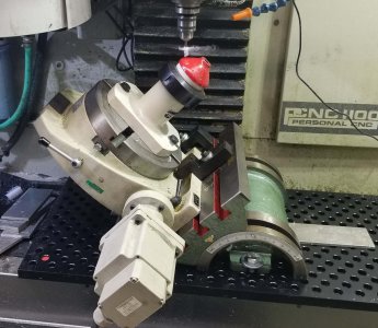
Sure like that CNC! Screw a boiler top in place, hit "START", and let the machine do the work!
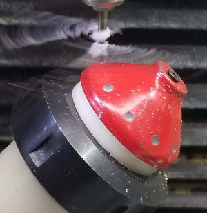
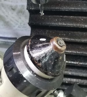
Had an issue about half-way through when I stripped the threads in the arbor. . . My bad, should have done my eventual fix in the first place. I took a 3/8”-16 bolt and tapped an 8-32 hole in the end for the set screw. Then drilled & tapped a 3/8”-16 hole in the arbor. Much sturdier with a steel threaded insert for the clamping screw.
Stripped out the plastic arbor 8-32 hole. So replaced the center with a 3/8"-16 bolt with an 8-32 hole in the end. Faced, center drilled, tap drilled and tapped the bolt.
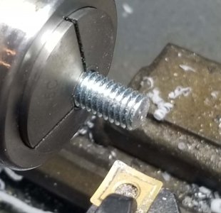
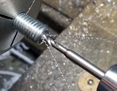
Mounted the arbor in a collet, then center drilled and tap drilled for a 3/8"-16
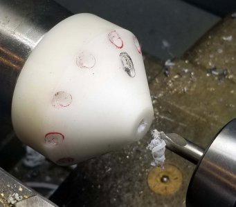
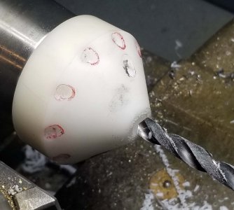
Tapped, then flipped to drill a 3/8" clearance hole for the shank of the bolt.
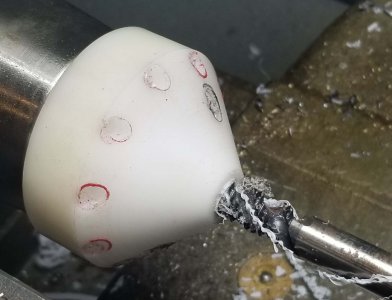
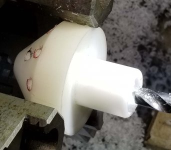
Threaded the bolt in place. Much more durable with a steel 8-32 hole for mounting the boiler tops
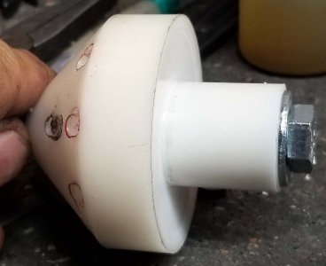
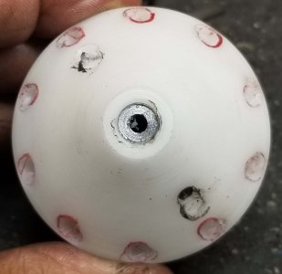
Just about had the parts done when I ran into another problem when the 4th axis table stopped indexing. Ended up finishing up by positioning the table by hand and locking it in place. Manually advanced the Z and X for the slots with a G1 command from the MDI line.
Pulled the stepper motor off the 4th axis and it just bounces back & forth when the A-axis is jogged. Time for a call to Tormach for some trouble-shooting. . .
Finished up the “HG” nose cones by punching a 0.257” hole (smallest punch I have over 0.250”) for the ¼” steel support rod. I don’t expect to get anywhere close to $56 per part, but hopefully enough to cover what I need to do to fix the 4th axis. . .
Punching the center clearance hole for the 1/4" support rod
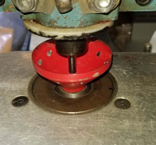
A few finished parts. Wish me luck on eBay!
Thanks for looking, Bruce
Germany’s Graf Zeppelin was all the rage as the large airship started a world tour in 1928. The A.C. Gilbert Company took advantage of the fervor by creating a toy copy of the Zeppelin in 1929. The 5’ long model was built from a super-structure of common and modified parts. A number of specific to the Zeppelin parts were introduced also.
Gilbert had introduced the boiler (cylindrical tube of steel) and boiler top in 1924. The boiler top was a steel cone that set on top of the boiler tube. The boiler top was modified to become the nose cone of the zeppelin model and was numbered part number “HG”.
Standard Erector set part number "U" boiler top

The original design used in 1929-30 sandwiched girders between two HG’s, a red-painted one on the outside and a black painted one on the inside. Two slots were cut into the parts for a pair of screws to hold the assembly together. The boiler top had a 5/32” hole through the center to accept a common axle rod. The zeppelin model was supported with a ¼” steel rod through the nose cone for display, so this hole was opened up to a little over ¼”.
1929/30 two-piece design


I suspect multiple hands were needed to tuck the ends of ten girders and the cloth bag between the two halves of the nose cone(s), then tighten the two screws. Gilbert simplified the design in 1931 with a one-piece nose cone with ten holes around the cone.
1931-32 one-piece design


Being a bit of a dirty filthy capitalist, I track auctions for these parts on eBay and maybe take them on if prices are favorable. Well, one of my old (?) reproductions showed up on eBay recently and sold for $56! I remember making up a dozen or so of them 10 or 15 years ago and selling them for around $15, so time to make some more! Naturally, getting to a $56 bid requires someone else to bid $55, and there’s no guarantee the two guys will battle it out again and get the price higher than it should be. Regardless, gave me a reason to get into the shop.
Don't know if this was one I made up a few years ago or not, but at $56 they're worth doing again. . .

I made these before by cutting a paper pattern that was glued to a boiler top, center punched the holes, then drilled the top. It worked OK and was a pretty quick set up. I took a lot different approach this time.
I have a Tormach 1100 with a 4th axis rotary table. Plan was to mount the 4th axis on an angle plate at a 45 and run a routine to pop in the hole(s) or slots while indexing the nose cone to each hole/slot. Sure, why use a 2-minute set up with a paper pattern when I can go the way overkill route!
Started by making an arbor to hold the nose cone. Chucked up a piece of UHMW PE and turned a shoulder to 1” diameter. This would go into a 1” 5C collet on the 4th axis. Flipped the PE, faced, center drilled, tap drilled and tapped a hole for an 8-32 screw to fasten the boiler top to the arbor. Then turned the taper on the arbor to fit the boiler top.
Started by turning a 1" shoulder on a 2" round for mounting in a 5C collet. Flipped in a collet, then faced, center drilled, tap drilled, tapped.


Gave my right hand a good work out on the compound to cut the taper

Final arbor with a boiler top in place

I figured as long as I had my crazy set up on the fixture plate, I might as well make some of each style. Mounted the arbor to the 4th axis 5C collet chuck and screwed an original part in place. Jogged the X to find the holes/slots on the original part. Then touched off on the sides of the collet chuck nut to find Y. G-code program was pretty simple; drill a hole, index the A-axis 36 deg. to the next one and repeat. Also ran a different routine for the slotted version; drilled a start hole for the slot, changed to an end mill and cut the slot.
Set up for the 4th axis. Mounted the rotary table to an angle plate.

Sure like that CNC! Screw a boiler top in place, hit "START", and let the machine do the work!


Had an issue about half-way through when I stripped the threads in the arbor. . . My bad, should have done my eventual fix in the first place. I took a 3/8”-16 bolt and tapped an 8-32 hole in the end for the set screw. Then drilled & tapped a 3/8”-16 hole in the arbor. Much sturdier with a steel threaded insert for the clamping screw.
Stripped out the plastic arbor 8-32 hole. So replaced the center with a 3/8"-16 bolt with an 8-32 hole in the end. Faced, center drilled, tap drilled and tapped the bolt.


Mounted the arbor in a collet, then center drilled and tap drilled for a 3/8"-16


Tapped, then flipped to drill a 3/8" clearance hole for the shank of the bolt.


Threaded the bolt in place. Much more durable with a steel 8-32 hole for mounting the boiler tops


Just about had the parts done when I ran into another problem when the 4th axis table stopped indexing. Ended up finishing up by positioning the table by hand and locking it in place. Manually advanced the Z and X for the slots with a G1 command from the MDI line.
Pulled the stepper motor off the 4th axis and it just bounces back & forth when the A-axis is jogged. Time for a call to Tormach for some trouble-shooting. . .
Finished up the “HG” nose cones by punching a 0.257” hole (smallest punch I have over 0.250”) for the ¼” steel support rod. I don’t expect to get anywhere close to $56 per part, but hopefully enough to cover what I need to do to fix the 4th axis. . .
Punching the center clearance hole for the 1/4" support rod

A few finished parts. Wish me luck on eBay!

Thanks for looking, Bruce
Last edited:

