Erich's Benchtop Gear Hobber Project

Copying this from the profile post I sent earlier...
https://www.ebay.com/itm/284766134232
Honestly, for the money, I'd have a hard time not trying the above supply ,and one of these:
https://www.ebay.com/itm/224716884063

I just ordered one of these big PWM units. I wanted to get a closer look at what they're doing in there. I do switching power for fun. Yeah, I know... :)

Anyway, to run a 12V motor from a 24V supply, just don't turn it over 50%... ;)

If you're worried about motor transient voltages, put an LC filter on the output of the PWM Module. Then you'd pretty much get DC out of the controller. It wouldn't be closed loop DC, but for what you're doing it might just fine.

Dan
 
I've been definitely looking at those speed controllers, plus a 12v power supply transformer. It isnt' quite clear to me what the power supply unit you're linking adds for me, can you explain?
 
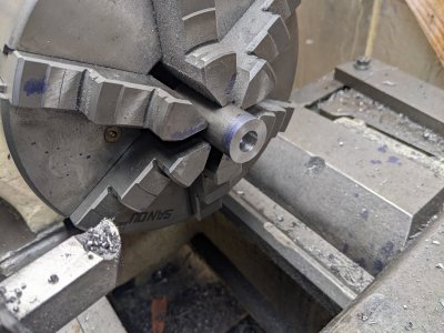
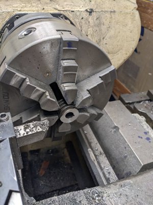
I did 1 part today, which is the ring that clamps the last fork into the housing/keeps everything in place. First, I faced and drilled 1/2" so it would slide on the shaft, into the end of some 1" 12L14.

PXL_20230110_220722999.jpg

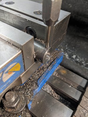
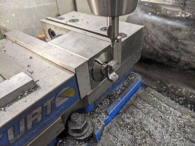
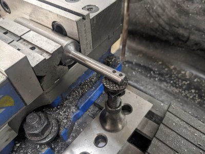
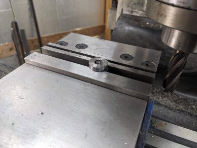
Next, I put it into the mill, and drilled for 2 8-32 set screws, per the plans. I again didn't part/split it off so that I could more easily make these drilled holes.

PXL_20230110_223421451.jpg

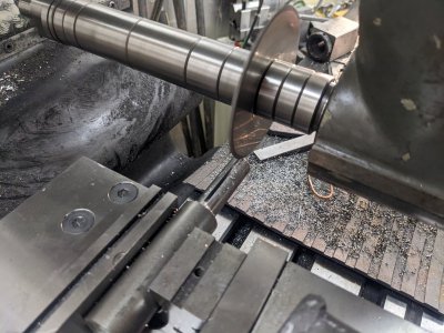
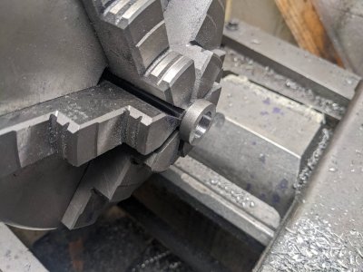
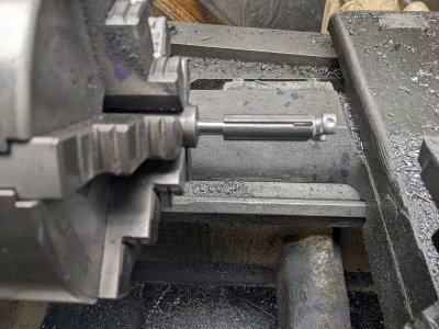
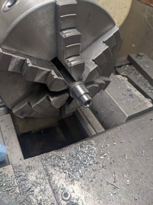
Then, back on the lathe, I parted it off:

PXL_20230110_223744605.jpg

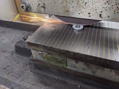
I finished it to length on the surface grinder, since I have a magnetic chuck. I pretty much could have done this on the lathe or mill if I cared to, but this was easy enough:

PXL_20230110_224632882.jpg

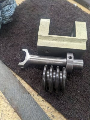
I ALSO had to shorten the gear that I got to make room for this. I considered using a smaller set screw, but I would have been down to a #2 or something silly like that, so I instead took ~150 thou off the gear in the lathe:
PXL_20230110_221526925.jpg

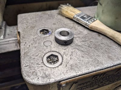
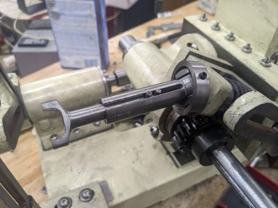
Here are all 3 in place:
PXL_20230110_224900807.jpg

I haven't assembled yet, since the gear is still a little tight on the shaft, and I haven't made a key. I might end up pressing the gear in place.

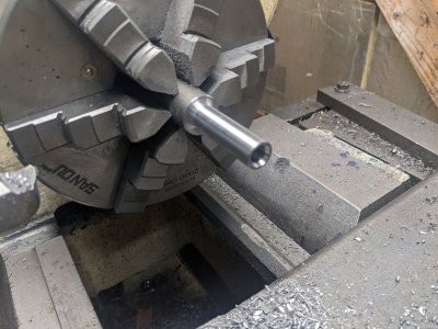
Next, I started on the next fork in the train (or at least, one of the middle ones). These use a sliding fit with a pin in the side to account for length changes. First, I turned the OD, reamed the ID on the lathe, and formed the back of the fork a bit. I once again left it on the same piece of stock to save me trouble later:

PXL_20230110_231159600.jpg


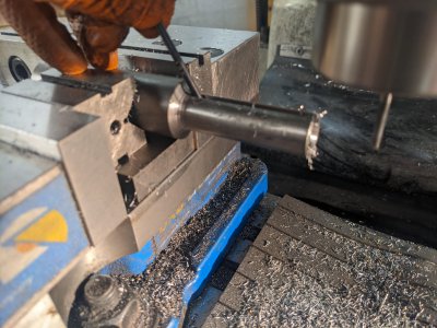
Next, I had to cut a 1/8" slot down the side. A pin will be pressed into the inner piece, and slide down this as the length changes. I COULD have done something boring like use an endmill. BUT @mattthemuppet2 hooked me up with a right angle attachment and large arbor (and an arbor support, but the arbor support doesnt fit my mill or the arbor... both are future projects). SO, no arbor support means I wanted to keep it as close to the head as possible.

I used a 3/32" cutter to rough out the slot:

PXL_20230110_234404874.jpg

I then used my 1/8" endmill to clean it up, and widen the hole a bit to make sure a .125 gauge pin slid nicely (AND, all the way to the end!).

PXL_20230111_000254599.jpg

I didn't get a chance to go further, a package showed up that I opted to unpack!
 
I've been definitely looking at those speed controllers, plus a 12v power supply transformer. It isnt' quite clear to me what the power supply unit you're linking adds for me, can you explain?
With speed controller you should be able to run the 12V motor from 24V. The PWM reduces the average voltage, at 50% PWM output, the output is 12V average. The motor shouldn't care if that average comes from 100% from 12V, or 50% from 24V. (You probably wouldn't want 10% from 120VDC tho, for example).

The only point about the supply is, that is most bang for the $$$ you'll probably get right now. I think those are around $1000 new, and the guy claims these are tested. You should be able to get that motor spinning with variable speed for under $75. That's pretty affordable...
It's the path I'd take if I needed to spin that motor.

Of course, this advise is worth exactly what you're paying for it... ;) LOL!
 
So I did a bit more work on the workpiece side, did an Ace run for parts, and did a little bit of fitting/assembly.

First, I finished up the piece from last time, the 'outer' sliding part. It started by forming the end on the lathe again like last time:

PXL_20230111_213411769.jpg

Then, using the mill to shape it and hit the divots for the set screws. I spent a little extra time with the ball nose endmill on this side to blend the bar and the fork, since the bar is a greater diameter on this one:

PXL_20230111_220215502.jpg

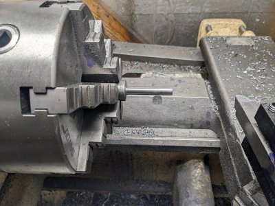
Next, I started on the part that slides inside of this one. It has a pair of pins to ride inside that slot, plus is a sliding fit inside. First was a quick turn down to 3/8":

PXL_20230111_222543660.jpg

AND a test slide:

PXL_20230111_222548652.jpg

Before parting, I took it over to the mill to drill 2 1/8" holes for the pins. They aren't through holes, so I drilled them with a 1/8" bit figuring I was loctiting them in place anyway. I don't have a 1/8" reamer anyway, so this is as good as I was going to get :) In retrospect, if I'd picked the pins up ahead of time, I could have tried an undersized drill bit and tried to fit it a bit better (or pressed it in!), since they turned out a touch loose:

PXL_20230111_223611593.jpg

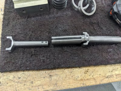
And here are the two finished pieces, plus the one that was already finished:

PXL_20230111_230231754.jpg

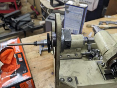
However, before I can start getting all that together, I figured I'd start assembling the work side. I assembled it first, though the shaft to gear is pretty tight. It wasn't a big deal, but meant assembling required a press, and disassembling a punch:

PXL_20230111_235943594.jpg

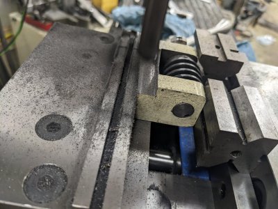
Upon assembly, I noticed the gears didn't mesh very well. First, because the flange on the bottom was hitting the bushing surround. This is my fault since I reversed the bushings I think, but a bit of time with the boring head in the mill cleaned that problem up:

PXL_20230112_003309789.jpg


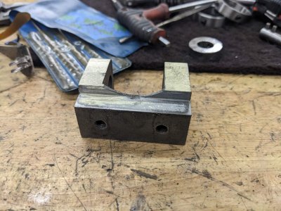
HOWEVER, a second attempt showed that the mesh still wasn't good, it was hitting the edge of those stops already before meshing. I ended up putting the U shaped piece on the mill and taking 100 thou off:

PXL_20230112_004352436.jpg


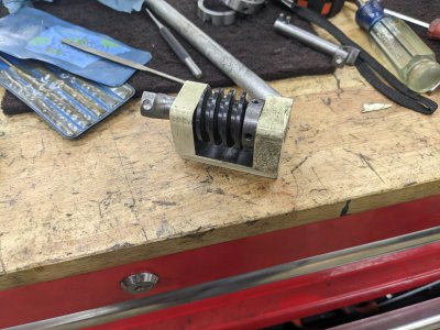
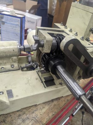
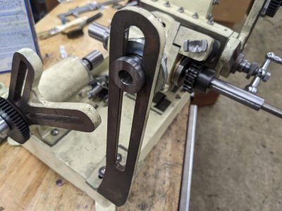
AND here it is assembled. The gears seem to mesh pretty well, and it is stopped on the 'gears' instead of the metal when fully meshed, so presumably that means i don't have any more material to remove:

PXL_20230112_004722224.jpg

AND that is it for now! 3 more pieces left to do on this linkage I think, then I can start on the other parts of my list!
 
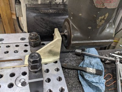
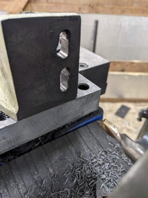
So I did 1 rework, plus two parts today. First, I decided to use the right angle head to cut slots into the "L" bracket.

PXL_20230112_220255004.jpg

UNFORTUNATELY I didn't realize that the right angle head changes the direction of rotation of the endmill. SO by the time I realized it, the endmill had wondered a bunch. Also, the lower hole was in the wrong place and had been enlarged before, so it looks ugly too. Fortunately, much of it hides under a washer. I might remake this someday, but its good enough for now.

PXL_20230112_220802926.jpg


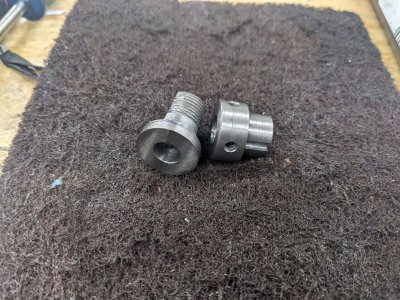
Next, I have two parts that go on the L-Bracket itself! One to hold the shaft in the right place, the other to hold the gear on the 'fork' as well.

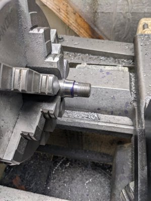
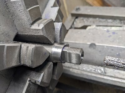
First is the one that holds it on the L bracket. This isn't too complicated, but has a 16 TPI thread. A quick time on the lathe got the OD turned to dimension, plus the threads done.

PXL_20230112_224117602.jpg

Before parting off, I popped it in the mill and flattened the sides, you'll see why in a moment. I didn't get a picture in the mill, but here it is after I put it in the lathe, and remembered to bore the inside .375.
PXL_20230112_225400037.jpg

A quick part off, then I popped it in the mill and faced it to thickness:
PXL_20230112_225646434.jpg

AND here it is installed with a nut on the L bracket:
PXL_20230112_230016856.jpg
PXL_20230112_230020585.jpg


Next, is the part that holds the gear on the last for section. I turned the OD:
PXL_20230112_231612823.jpg

I had to bore it .375 as well, then added a pair of set screws and a keyway. I turned it in the lathe, and faced it to length:
PXL_20230112_233540016.jpg

AND that was my day! I did a little bit of assembly on the linkage, and played with it a little:

PXL_20230112_233946280.jpg


The joint gets stuck a little, so I am likely going to have to round over some of the insides of the 'forks' a bit with some files, but it seems to turn reasonably smoothly!
 
I probably would have done a little more work, but the LAST piece I have to make is the fork, and I don't have a piece of 12L14 long enough. I've got some on order, but its not showing up till the weekend, so I probably won't get to it until next week.
 
It's OK. I'll be out of town so I can't watch.
 
@dkemppai : I ended up buying the speed controller you suggested, and found a similar power supply that was 12v instead of 24v, AND only $20! Same brand and similar size.

Looks like I'll have to make a box for all the power stuff at one point, but at least I have the power hardware picked up :)
 
@dkemppai : I ended up buying the speed controller you suggested, and found a similar power supply that was 12v instead of 24v, AND only $20! Same brand and similar size.

Looks like I'll have to make a box for all the power stuff at one point, but at least I have the power hardware picked up :)

That was a good deal on the power supply. Just a heads up, some of those supplies require a jumper to be installed before they make power. Users manual will of course cover the details.

I received the speed controller, although I haven't had a chance to look it over. One of these evenings I'll pull out some bench supplies and a dummy load, and light it up.
 
Back
Top