Erich's Benchtop Gear Hobber Project

Been looking at this kit for a few years now.
The hobber looks pretty nice! The plans are 5/10, but the castings are beautiful. I'd suggest getting it now so you can follow along with my build :)

If you can convince a few others, I could talk Gary into a group buy.
 
Alright, another interesting day, this time I tackled and finished the 'base'. Usually I would do something like this first, but wasn't convinced right away I had all the necessary dimensions.

First, despite what the plans say (which is not to!), I opted to flatten the feet. I figure it was counting on a single setup in the mill to do the whole top, and I did it in 2 operations. I couldn't get it to sit flat enough on the mill without doing this, but when done, I was perfectly flat:

PXL_20220906_205613134.jpg

Next, I flipped it over and used a wiggler to find a straight-ish part of the casting flats to set my zeros:

PXL_20220906_211339096.jpg

SO the big important thing I figured out is what is the important dimensions. FIRST, there is 3 pads. The hole patterns inside each one are critical, but the dimensions between them are NOT critical, with 1 exception. The MOST critical part is that they are all 'square' to each-other, so it is important to do all the holes/etc in 1 setup.

The ONE important relationship is that the bottom left and top left pads share a left-side 'zero'. Additionally, the dimensions on the top-left (the .750 from the RHS of the flat) ACTUALLY should be relative to the LHS of the flat. THis is because the relationship between the 'EL' piece we made earlier and the hob-holder spindle are important.

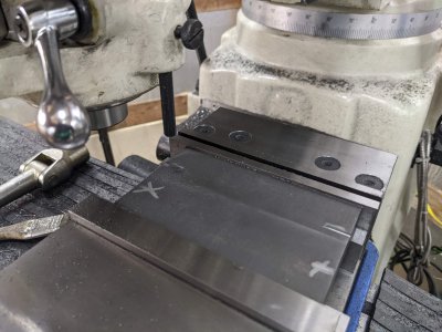
I started by drilling/tapping the lower-left, and convinced myself I got it right enough to move on. Then I started the upper left by cutting the groove for the keystock. Plans call for just a piece on each side for this one, but I chose instead to cut it all the way across, so I could use a single piece if I cared to.

PXL_20220906_213728604.jpg

Finally, I drilled/tapped the holes in it, and this pad was done!

PXL_20220906_220125441.jpg

The lower right went similarly, and centered the stuff on the pad rather than try to make it relative to the other two pads (which wasn't on the plans anyway!).

I drilled the holes (not tapped, the bolts come in from the bottom!), and cut the keyway slot in this one too. Note that I COULDN'T go all the way across, because for some reason the key would go through the 3 bottom mounting holes.

I DID have a minor oopsie on this one as you can see to the left of the left key-stock slot. While raising the table to cut the final cut, I nipped into the top of the casting ~2 thou. I'm hopeful no one here will tell on me once this gets painted :D

PXL_20220906_222535190.jpg


SO, the base is done! I couldn't find my stash of 1/4-20 bolts to pop the two other parts onto this in the meantime, so thats all the pics I have today.

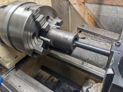
ADDITIONALLY, I started to try to setup for the hob-spindle-holder stuff since my bearings were on their way, but I couldn't get my 6 jaw off the lathe! I suspect that is going to be my next big thing. Mixed with the pass-around-box showing up today, I wasn't going to get anything else done :)
 
So, two steps back kinda day:/ I wanted to get one side of the features set up right on the gear hobber spindle holder. It took ages to get the first setup right in the 4 jaw, but I got it where I was somewhat happy with it. Unfortunately I had a momentary lapse, and crashed into the face while cutting the outside diameter.

I just couldn't get it back in place either right, and attempts to recut just ended up making the part too thin. Finally, turns out my facing job is likely not square, so I would have to do that again too.

I decided to scrap the part, and I'll have to try it again. My thought is to try to use the mill and boring head for as much as I can next time, since the work holding is easier. Sadly, that is harder to get a square inside face on the bores, but they are less important than the diameters.

I figure I'll get through as many castings as I can before reordering to save myself multiple drives or an extra shipping box.

So next time I'll work on a different part.
 

Attachments

  • PXL_20220907_221636276.jpg
    PXL_20220907_221636276.jpg
    554.4 KB · Views: 34
So, two steps back kinda day:/ I wanted to get one side of the features set up right on the gear hobber spindle holder. It took ages to get the first setup right in the 4 jaw, but I got it where I was somewhat happy with it. Unfortunately I had a momentary lapse, and crashed into the face while cutting the outside diameter.

I just couldn't get it back in place either right, and attempts to recut just ended up making the part too thin. Finally, turns out my facing job is likely not square, so I would have to do that again too.

I decided to scrap the part, and I'll have to try it again. My thought is to try to use the mill and boring head for as much as I can next time, since the work holding is easier. Sadly, that is harder to get a square inside face on the bores, but they are less important than the diameters.

I figure I'll get through as many castings as I can before reordering to save myself multiple drives or an extra shipping box.

So next time I'll work on a different part.
I'm curious about the padding on your 4 jaw setup with this. One pair of jaws is inverted. I'm not exactly following what you intended with this setup.
 
I'm curious about the padding on your 4 jaw setup with this. One pair of jaws is inverted. I'm not exactly following what you intended with this setup.
My problem was that I needed the step jaws as a flat surface to reference the flat face on the back. However, if I used all 4 step jaws, even with a bunch of packing, the jaws were interfering. So by swapping that one around, it didn't hit the side two (or vice versa).
 
SO I did some work with the first/lowest 'slide' on Thursday, and finally have time to type about it :)

This is a casting that bolts to the base, and ends up being the fixed slide for the longitudinal motion. I don't have the ball-endmill to get this done, but started it anyway.

First I stood it straight up and cleaned up a 'small' edge. Next, I faced the bottom:

PXL_20220908_213227566.jpg

About 40-50 thou off of it, and it was pretty well cleaned up.


Next, I flipped it over, and did the top, machining to final thickness.
PXL_20220908_215628908.jpg

Then I did the short sides this way.
PXL_20220908_220054198.jpg

Finally, I machined to width by standing it up. (no picture).

My last operation of the day was the two slots for keystock, and drilling and tapping the holes used to mount it to the base:

PXL_20220908_224741371.jpg

Next time I'm in the shop, I'll likely have my ball-endmill to cut the center relief, plus the dovetail cutter to get that all done right too. I'll probably skip the 'nut mount' for a bit, until I have the nut part made and ready to match-machine.
 

Attachments

  • PXL_20220908_222741835.jpg
    PXL_20220908_222741835.jpg
    370.4 KB · Views: 17
I FINALLY got a chance to get back to the project after quite a while. I decided to spend today doing some more work on the longitudinal cross slide.

First, I needed a relief with a ball endmill down the center:

PXL_20220920_212710263.jpg

This is just clearance for the lead screw. Next, I needed to cut the dovetails on it. They need to be coplaner/etc, but otherwise the dimensions don't really matter all that much (AND aren't well defined in the diagrams/in a way that can be measured well). There is an adjustable brass gib that goes on 1 side and makes one side 'deeper' than the other by about 150 thou. Otherwise, this went easy enough.

PXL_20220920_214344047.jpgPXL_20220920_222354421.jpgPXL_20220920_224134192.jpg

There is 1 more step on this piece (a place to mount the 'nut'), but I'm holding off until I can make the nut, and bore the spot to fit.
 
Alright, slight detour today. The last thing I have to do to the bottom slide is cut room for the nut to mount. However, I decided to make the nuts first.

The plans suggest modifying a set of $40/each nuts from McMaster, which I DID, but probably would not have done again. I should have just bought the material and a tap.

First, I indicated a piece of allthread in the 4 jaw:PXL_20220922_210812304.jpg

Mounted the nut from McMaster:
PXL_20220922_210922408.jpg


PXL_20220922_211838431.jpg
Then turned it to shape. As you can see.

PXL_20220922_213138927.jpg

Most of the material from McMaster was wasted, and the thread wasn't centered very well in it anyway! If I were to do it again, I'd just buy raw stock and make it myself. Probably would have been more accurate, since I could turn the OD and do the thread in a single op.


Next step was to turn the top into a flange with room for #4 screws. One of the dimensions on the plans was wrong (it says the flange should be 1.084*.650, but elsewhere it has me make a .625 pocket!), So this was corrected.

PXL_20220922_220945471.jpg

And, all done! That's it for today :)

PXL_20220922_224034008.jpg
 
Alright, my wife took longer than I expected to get home, so I got a little more work done. I decided to finish the slide.

I stood it up in the vise, and prayed it would be stiff enough. I edge found, center drilled, then did a .375 stubby about to the right distance. The bottom of the hole chartered a bit, but clearance for a boring bar was done :)
PXL_20220922_234032239.jpg


Next, some long cuts on power feed with the boring head. Ended up getting about the nicest slip fit I could hope for! The chatter near the bottom of the hole cleared up for the most part
PXL_20220922_235126965.jpg

Next, I cleared out room for the flange:
PXL_20220923_001840083.jpg

And drilled/tapped #4-40 for the mounting screws:
PXL_20220923_002932212.jpg

I don't have the screws I need yet, but here it is slipped into place:
PXL_20220923_003033023.jpg

This makes the bottom slide all done!
 
Back
Top