-
Welcome back Guest! Did you know you can mentor other members here at H-M? If not, please check out our Relaunch of Hobby Machinist Mentoring Program!
You are using an out of date browser. It may not display this or other websites correctly.
You should upgrade or use an alternative browser.
You should upgrade or use an alternative browser.
Erich's Benchtop Gear Hobber Project
- Thread starter ErichKeane
- Start date
- Joined
- Aug 3, 2017
- Messages
- 2,437
Got picture happy today, and also got a whole part done! The WRONG part, but a whole one. I started by trying to work on the longitudinal slide, the other half of the dovetail I did above.
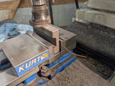
First, I faced 1 side:
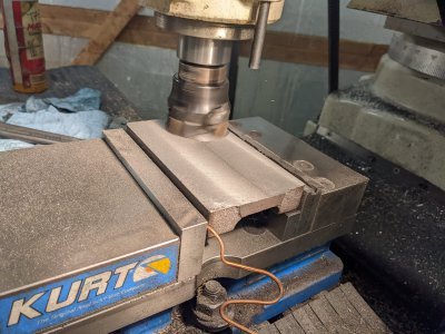
Then, skimmed the back as thin as I could:
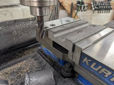
I flipped it to start the dovetail, but got 1 of the long dimension sides done too while I had a chance!
Then, I went to set the depth of the dovetail. I noticed that I couldn't clean up the whole casting. Additionally, I ALSO noticed that the casting number was FOUR, not THREE! Fortunately, both are identical in dimension and purpose, except for the features on top. However, in case someone looks at the casting number I couldnt clean up someday, I decided to finish this one as the feed slide.
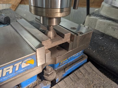
I used the DRO to get the dovetail centered and to width, as the dimension was specified at the BOTTOM point of the dovetail! Oh ,well, depth and centered is most important, and the DRO got the width right.
Next I did the top face. This is where the two slides differ: this one uses a pin and 2 1/4-20 bolts to allow the gear to sit at an angle. Simple enough with the DRO.
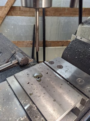
The next thing I needed was the mount for the lead screw bracket. Two 1/4-20 holes centered on the dovetail is all that took.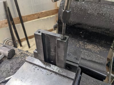
Next, the gib tightening screws and alignment pin. The plans switch between #6 and #8-32 depending here, but I decided to just do #8 on the whole thing.
The plans also say to use a 1/8" pin hole, but I only have a 3/16" reamer: so that's what I'm going with
Also, the holes were on .915" centers, which was strange, and didn't really leave the ends even, but I figured there might be a good reason for it, so I had a sheet of paper with all the measurements for exactly that reason
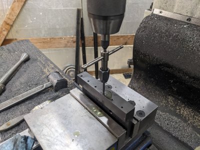
And that's it! Part is done: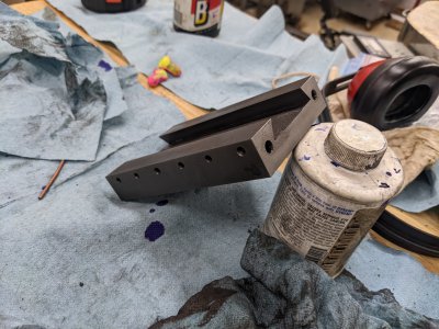
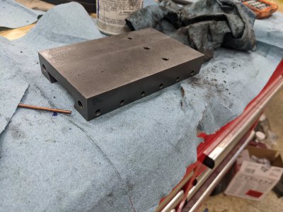
Not the part I set out to make, but a part off the list anyway. Next I'll probably go do the part I intended, though I'll take fewer pics, since it is the same part more or less.
First, I faced 1 side:

Then, skimmed the back as thin as I could:

I flipped it to start the dovetail, but got 1 of the long dimension sides done too while I had a chance!

Then, I went to set the depth of the dovetail. I noticed that I couldn't clean up the whole casting. Additionally, I ALSO noticed that the casting number was FOUR, not THREE! Fortunately, both are identical in dimension and purpose, except for the features on top. However, in case someone looks at the casting number I couldnt clean up someday, I decided to finish this one as the feed slide.
I used the DRO to get the dovetail centered and to width, as the dimension was specified at the BOTTOM point of the dovetail! Oh ,well, depth and centered is most important, and the DRO got the width right.

Next I did the top face. This is where the two slides differ: this one uses a pin and 2 1/4-20 bolts to allow the gear to sit at an angle. Simple enough with the DRO.

The next thing I needed was the mount for the lead screw bracket. Two 1/4-20 holes centered on the dovetail is all that took.

Next, the gib tightening screws and alignment pin. The plans switch between #6 and #8-32 depending here, but I decided to just do #8 on the whole thing.
The plans also say to use a 1/8" pin hole, but I only have a 3/16" reamer: so that's what I'm going with
Also, the holes were on .915" centers, which was strange, and didn't really leave the ends even, but I figured there might be a good reason for it, so I had a sheet of paper with all the measurements for exactly that reason

And that's it! Part is done:


Not the part I set out to make, but a part off the list anyway. Next I'll probably go do the part I intended, though I'll take fewer pics, since it is the same part more or less.
- Joined
- Aug 3, 2017
- Messages
- 2,437
Heh, so turns out it was fortunate I got the wrong part  The 'correct' part ends up needing a T-slot of a bizarre set of dimensions that I can't really find a cutter that will cut. It is only 3/8" wide, but has a 3/4" 'flange', only 1/8" thick.
None of the woodruff cutters are a size that I think looks good, so I ordered a cheap T slot cutter on amazon that I'm hopeful I can turn into a good T-slot.
SO, if I get time to work today, I'm likely going to work on a different part while I wait for my T slot cutter. It would be nice to have one that will take me a few days, so I'm not waiting around too long, or delaying the other part while my notes from the other part are still readable
- Joined
- Aug 3, 2017
- Messages
- 2,437
So as promised, I did a different part today! This is two dovetail slide parts as 1 casting! The piece I made last night goes on 1 side, and the other attaches up/down on an angle plate. This makes up the "up/down" and "feed" adjustment.
First, I hit it with a file to get this to work then with some copper wire packing material, got it so I could start machining it in the vise.
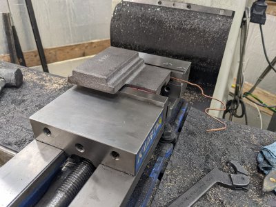
First I squared off the whole part, which I can use for index surfaces later.
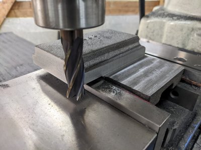
Next, I tried to cut the dovetail. Unfortunately, right as I finished, I realized that SOMETHING moved. I strongly suspected the fit in the vise, so instead of fixing it, I opted to do the other block FIRST, so I would have a good clamping spot.
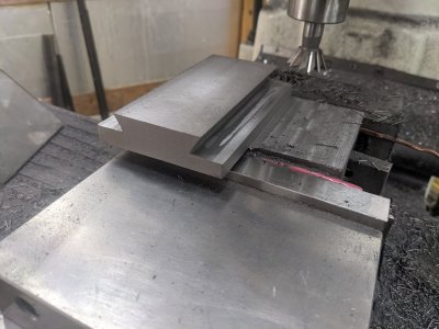
Also, I over cut the bottom(left here) thanks to a math issue (the plans are nuts with how they dimension this...), So I'll have to fix that too.
As mentioned, I flipped it over, did the outside dimensions, then cut this dovetail. This one was pretty easy going: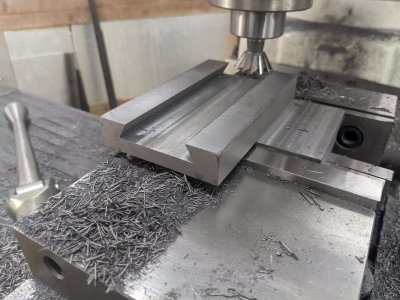
Then I flipped it back over, and cut the bad dovetail again. I had to cut a good amount deeper, AND thanks to my transcription error, 40 thou "high", but this went well enough as well:
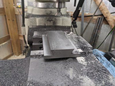
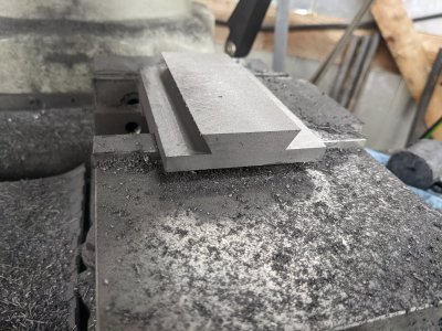
I also faced the top to get the dovetail heights right, but I suspect I'll have to take a few thou out of this somewhere at one point, since the plans seem like they will interfere. I'll likely get some surface grinder time during assembly
Next, I cut the relief for the lead screw. However, I thought the depth was a mistake in the plans so I cut it too shallow. I did not notice until I tried to assemble stuff, but I'll be able to get it right easy enough best time I'm working on this.
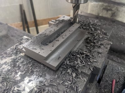
I spent some time with the boring head for the nut:
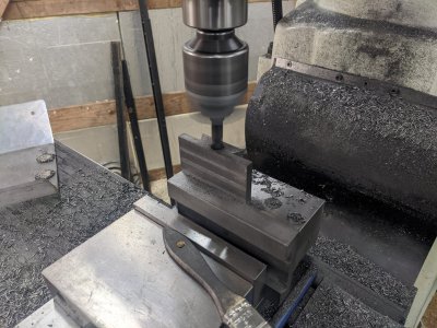
Then machined the relief for it, plus the screw holes. So, this half of the part is done. I just need another bit of time doing the mount holes + gib screws on the other side.
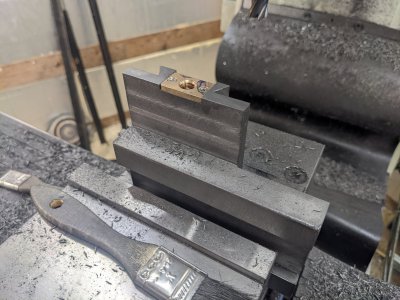
So, reasonably successful day. I need another hour on this part, then I can call it done
First, I hit it with a file to get this to work then with some copper wire packing material, got it so I could start machining it in the vise.

First I squared off the whole part, which I can use for index surfaces later.

Next, I tried to cut the dovetail. Unfortunately, right as I finished, I realized that SOMETHING moved. I strongly suspected the fit in the vise, so instead of fixing it, I opted to do the other block FIRST, so I would have a good clamping spot.

Also, I over cut the bottom(left here) thanks to a math issue (the plans are nuts with how they dimension this...), So I'll have to fix that too.
As mentioned, I flipped it over, did the outside dimensions, then cut this dovetail. This one was pretty easy going:

Then I flipped it back over, and cut the bad dovetail again. I had to cut a good amount deeper, AND thanks to my transcription error, 40 thou "high", but this went well enough as well:


I also faced the top to get the dovetail heights right, but I suspect I'll have to take a few thou out of this somewhere at one point, since the plans seem like they will interfere. I'll likely get some surface grinder time during assembly
Next, I cut the relief for the lead screw. However, I thought the depth was a mistake in the plans so I cut it too shallow. I did not notice until I tried to assemble stuff, but I'll be able to get it right easy enough best time I'm working on this.

I spent some time with the boring head for the nut:

Then machined the relief for it, plus the screw holes. So, this half of the part is done. I just need another bit of time doing the mount holes + gib screws on the other side.

So, reasonably successful day. I need another hour on this part, then I can call it done
- Joined
- Aug 3, 2017
- Messages
- 2,437
So, did some work and finished the piece from yesterday, so started another casting, and afraid I messed it up good! Could use advise on work holding!
First, the two-at-90 degrees casting. I enlarged the lead screw relief, theb set it up to drill/tap for the mount for the lead screw on the other side:
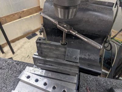
Next, I drilled, tapped/reamed the holes for the gib screws and pin;
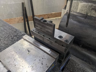
And, part complete!
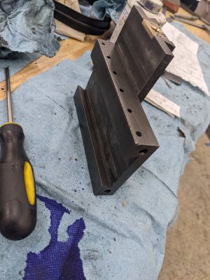
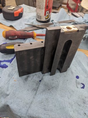
So, next I decided to try the angle plate portion. This is a work holding nightmare. Thanks to the web, it doesn't really fit in my vise any way, but I started by just holding it by the web with some copper wire:
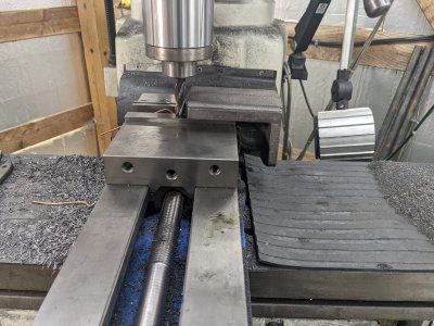
It is as far left as possible in this pic. I was able to get 3 of the sides plus top milled, but left the other side to do on the shaper once I'm done, as I don't have a endmill that can do this in 1 pass.
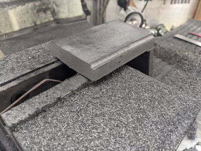
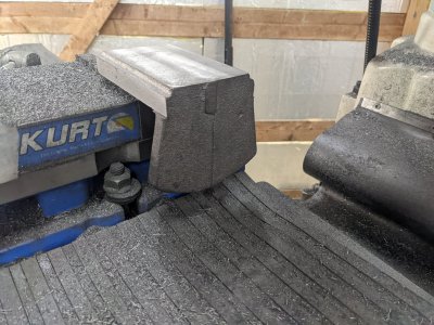
Next, I started cutting the dovetail:
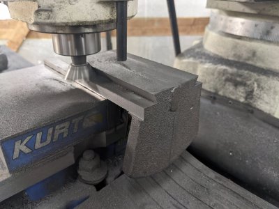
Things were going nicely, and I got within 150 thou of one of the dimensions, taking 50 thou full depth cuts, and all was going fine. Then, disaster: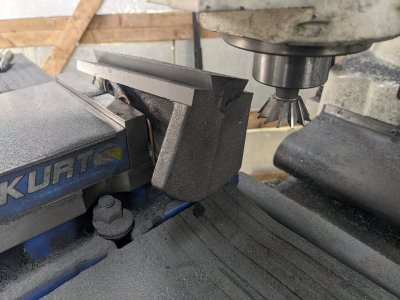
The gouge is something that won't be a problem, but the loss of setup IS a problem!
I just don't have a good way of setting this back up in the vise. My ONLY idea at the moment is to put the big vise back on the shaper and hold it by the sides, and try to cut my first dovetail on a shaper. I've never done it successfully before, but I guess there is a first time for everyone?
Anyone have a better idea? What should I be thinking of?
First, the two-at-90 degrees casting. I enlarged the lead screw relief, theb set it up to drill/tap for the mount for the lead screw on the other side:

Next, I drilled, tapped/reamed the holes for the gib screws and pin;

And, part complete!


So, next I decided to try the angle plate portion. This is a work holding nightmare. Thanks to the web, it doesn't really fit in my vise any way, but I started by just holding it by the web with some copper wire:

It is as far left as possible in this pic. I was able to get 3 of the sides plus top milled, but left the other side to do on the shaper once I'm done, as I don't have a endmill that can do this in 1 pass.


Next, I started cutting the dovetail:

Things were going nicely, and I got within 150 thou of one of the dimensions, taking 50 thou full depth cuts, and all was going fine. Then, disaster:

The gouge is something that won't be a problem, but the loss of setup IS a problem!
I just don't have a good way of setting this back up in the vise. My ONLY idea at the moment is to put the big vise back on the shaper and hold it by the sides, and try to cut my first dovetail on a shaper. I've never done it successfully before, but I guess there is a first time for everyone?
Anyone have a better idea? What should I be thinking of?
- Joined
- Aug 3, 2017
- Messages
- 2,437
I had another idea: I ordered some 3" tall soft-jaws, and am going to mill in a 'step', then use the two milled sides to hold it in place. Hopefully being able to move it left most of the way will made a sufficient difference to make this worth-while.
- Joined
- Aug 3, 2017
- Messages
- 2,437
Moved onto a different part today, and only had about an hour and a half. This is the longitudinal slide I accidentally didn't do before 
I got the outer shape done, did the dovetails, and moved onto the angle plate pivot bolt slot. The plans are wacky here, seemingly implying this should be a T nut and the dimensions are way off for it, so I came up with my own. Plunged with a 1/4" end mill, then widened each side 10 thou.
Then used a 5/8" endmill to make a .750 approx area for the washer. I would have used a .750 end mill, but I can't find my 3/4" r8 collet! Off to internet's to find one
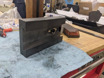
I still have to do gib screws/pin, lead screw mounting bolts, and t-slors, but the first two should take a short time tomorrow. AND my tslot cutter is supposed to come in this evening, so I can plan the slot around it.
I got the outer shape done, did the dovetails, and moved onto the angle plate pivot bolt slot. The plans are wacky here, seemingly implying this should be a T nut and the dimensions are way off for it, so I came up with my own. Plunged with a 1/4" end mill, then widened each side 10 thou.
Then used a 5/8" endmill to make a .750 approx area for the washer. I would have used a .750 end mill, but I can't find my 3/4" r8 collet! Off to internet's to find one

I still have to do gib screws/pin, lead screw mounting bolts, and t-slors, but the first two should take a short time tomorrow. AND my tslot cutter is supposed to come in this evening, so I can plan the slot around it.
- Joined
- Aug 3, 2017
- Messages
- 2,437
Welp, I'm a big dummy  The T slot cutter I bought is a 10mm shank, so a 10mm R8 collet will be here early next week! SO I'll have to put this part aside as well after another ~hr of work until next week.

