

-
Welcome back Guest! Did you know you can mentor other members here at H-M? If not, please check out our Relaunch of Hobby Machinist Mentoring Program!
You are using an out of date browser. It may not display this or other websites correctly.
You should upgrade or use an alternative browser.
You should upgrade or use an alternative browser.
Erich's Benchtop Gear Hobber Project
- Thread starter ErichKeane
- Start date
- Joined
- Aug 3, 2017
- Messages
- 2,437
This can cut DP gears, but I dont know about worms. I'm not sure how that would work?Can we back track a little? I am confused as to how this device works. Can this cut DP gears as well as driven worm gears? How do you cut a straight gear with a hob that has a spiral pitch?
As far as how to cut a straight gear, I don't really 'get it' yet
 I THINK the fact that the gear is spinning as well makes it work? Here is a video of it running:
 - Joined
- Mar 25, 2013
- Messages
- 4,614
I think I see now. The gear blank is angled with respect to the hob which cancels out the pitch of the hob.
If you wanted to make a gear to be driven by a worm you would just keep the blank at 90 deg and the pitch of the hob would have to match the pitch of the intended worm.
If you wanted to make a gear to be driven by a worm you would just keep the blank at 90 deg and the pitch of the hob would have to match the pitch of the intended worm.
Everything You Wanted to Know About Gear Hobbing - Federal Gear
If you know anything about gear manufacturing, you’re probably somewhat familiar with hobbing. But if you’re new to the game, it may sound like a strange term. Hobbing is an important machining process that allows manufacturers like Federal Gear to cut precision gears from raw materials. It’s...
fg-machine.com
- Joined
- Aug 3, 2017
- Messages
- 2,437
Ah, that makes sense!I think I see now. The gear blank is angled with respect to the hob which cancels out the pitch of the hob.
If you wanted to make a gear to be driven by a worm you would just keep the blank at 90 deg and the pitch of the hob would have to match the pitch of the intended worm.
Everything You Wanted to Know About Gear Hobbing - Federal Gear
If you know anything about gear manufacturing, you’re probably somewhat familiar with hobbing. But if you’re new to the game, it may sound like a strange term. Hobbing is an important machining process that allows manufacturers like Federal Gear to cut precision gears from raw materials. It’s...fg-machine.com
As designed, I don't think this could do worms, I'd have to do that on my lathe
BUT, it should be able to make enough gears for itself, and kill my time as a shop project, so it'll accomplish my goals at least Fortunately, there is a local group for model machinists (I haven't got out to a meeting yet!), where both the designer and plans maker are members, so hopefully I'll have resources to get the answers I need.
I STILL have no idea how the lead-screws work for any of the three axes (though 2 are the same!), but that is a problem for 'later Erich'.
The nice part is I'm getting close on castings. Once I get the angle plate, I'll have what I consider the 'main tower' done (though lead-screw brackets I'm holding off until I have the lead screws made, as well as the feed-gear quadrant which I'm holding off until the lead-screw bracket is done!).
I still need a replacement hobb-spindle housing casting, which after I do THAT, i can do the quadrant for it, and that would be all the castings.
ONE BIG QUESTION I haven't answered for myself: The plans are designed around an NMTB-20 for the hobb and work spindle centers. I don't seem to be able to find one of these AT ALL, they are basically unobtainable from what it looks like. They DO have drive-dogs, which are nice.
I DID find an old forum post at one point, where the author of the plans mentions that the 'original' (this is a modified version of the one @vtcnc is working on!) was based around MT2. This ends up making a couple of parts a little simpler, lets me use a reamer to get the taper, AND makes for cheap MT2 'blanks' as my tool/hobb holders, which is very tempting. So I'm leaning THAT way.
A SECOND (smaller) QUESTION: Is how to figure out which gear sizes I need, and where to put them to make stuff work.
AND A THIRD, smaller/later QUESTION: What sort of motor I see myself using for this. I went to the electronics-scrap store yesterday to see what they had, and there wasn't anything great (though I DID impulse buy an O-scope, so....). I THINK a treadmill motor is going to be too big, and I don't have a good idea of what size motor to use...
Basically, I'm leaving all of those questions for "later Erich" at the moment, but I figured folks here might have a useful opinion on each!
- Joined
- Aug 3, 2017
- Messages
- 2,437
So a bit of progress today, but a bit of a mess up too, which hopefully I can fix easy enough.
First, I installed the new aluminum tall jaws I ordered. There was zero machining done on these, they are as extruded! Oh well, flat/straight enough, and I'll mill them like soft jaws instead.

I faced the top, then tightened the vice and ran a 5/8" endmill down the center, 1/4" deep.
 These were enough to hold the part firmly enough. I had previously flattened the sides, but I wasn't able to get the top face closer than about 10thou. So, I faced the top down a bit:

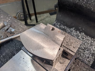
Then, in the same setup, I cut the dovetails finally to size:

I screwed up here and removed all of it from the vise and swapped the jaws.... Then I noticed that I forgot the lead screw relief, so I had to swap the jaws back in, set it up and cut it out with a ball endmill. I had to plunge cut, since the casting didn't have the space cast out of it this time:

Once everything was back and the vise was re-indicated in, I faced the bottom. I had quite a bit to take off, but left it thick:

As you can see, most of my crash earlier came out, but not all! There is a tiny fingernail sized sliver left:

Here is where I messed up. I found my center point and started drilling. BUT I thought this was for the brass nut, instead of the 1/4-20 hole. I got a 1/2"+ sized hole before I realized it.
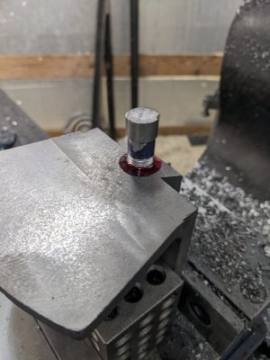
I opted to patch it with a 9/16-18 threaded piece, as I had that tap handy! It power tapped with only the 1/2" drill bit, which was fortunate as otherwise I would have needed the boring head.
Next, I grabbed a piece of 12L14 I had that was 5/8", turned it down a bit under 9/16", and single pointed some threads. I didn't have a nut to test it with, but I figured I'd press my luck cutting by eye (basically until the blue got razor thin).

Fortunately it fit just right! I used a ton of loctite red to lock it into the hole. I called it a night or give the loctite time to cure, and for me to stop being a dunce.
First, I installed the new aluminum tall jaws I ordered. There was zero machining done on these, they are as extruded! Oh well, flat/straight enough, and I'll mill them like soft jaws instead.
I faced the top, then tightened the vice and ran a 5/8" endmill down the center, 1/4" deep.
These were enough to hold the part firmly enough. I had previously flattened the sides, but I wasn't able to get the top face closer than about 10thou. So, I faced the top down a bit:Then, in the same setup, I cut the dovetails finally to size:
I screwed up here and removed all of it from the vise and swapped the jaws.... Then I noticed that I forgot the lead screw relief, so I had to swap the jaws back in, set it up and cut it out with a ball endmill. I had to plunge cut, since the casting didn't have the space cast out of it this time:
Once everything was back and the vise was re-indicated in, I faced the bottom. I had quite a bit to take off, but left it thick:
As you can see, most of my crash earlier came out, but not all! There is a tiny fingernail sized sliver left:
Here is where I messed up. I found my center point and started drilling. BUT I thought this was for the brass nut, instead of the 1/4-20 hole. I got a 1/2"+ sized hole before I realized it.
I opted to patch it with a 9/16-18 threaded piece, as I had that tap handy! It power tapped with only the 1/2" drill bit, which was fortunate as otherwise I would have needed the boring head.
Next, I grabbed a piece of 12L14 I had that was 5/8", turned it down a bit under 9/16", and single pointed some threads. I didn't have a nut to test it with, but I figured I'd press my luck cutting by eye (basically until the blue got razor thin).
Fortunately it fit just right! I used a ton of loctite red to lock it into the hole. I called it a night or give the loctite time to cure, and for me to stop being a dunce.
Attachments
- Joined
- Aug 3, 2017
- Messages
- 2,437
Alright, busy day! First I used an end mill plunge cutting through my repair to get it just below flush:

Then drilled and tapped 1/4-20" for it's mounting bolt:

I wasn't confident I could get this on the rotary table in a stiff enough way, so I once again used the bolt circle tool, cutting every 2.5 degrees:

Then, a file and some elbow grease got the bolt sliding. I'll probably spend a few more minutes on this at one point:

After that, I cut the area for the nut like before, and that is all there is to this part!


Next, the lead screw bracket castings:
I cut them apart, then milled the top and back.

I was not convinced that the lead screw setup will actually WORK as specified, so I pulled up FreeCAD and modeled it.
I realized that my mental model of these parts was reversed, so good thing I modeled before cutting!
I also think that I know how to modify the plans to make two of the three leadscrews work!
AND, enough that I can cut these castings. BUT that is for another day.
Then drilled and tapped 1/4-20" for it's mounting bolt:
I wasn't confident I could get this on the rotary table in a stiff enough way, so I once again used the bolt circle tool, cutting every 2.5 degrees:
Then, a file and some elbow grease got the bolt sliding. I'll probably spend a few more minutes on this at one point:
After that, I cut the area for the nut like before, and that is all there is to this part!
Next, the lead screw bracket castings:
I cut them apart, then milled the top and back.
I was not convinced that the lead screw setup will actually WORK as specified, so I pulled up FreeCAD and modeled it.
I realized that my mental model of these parts was reversed, so good thing I modeled before cutting!
I also think that I know how to modify the plans to make two of the three leadscrews work!
AND, enough that I can cut these castings. BUT that is for another day.
- Joined
- Aug 3, 2017
- Messages
- 2,437
SO, I've attached a render of the lead-screw extension + everything else in case it helps anyone. It is a .html canvas, so anyone with a browser can look around! You can see the color scheme in the upper right of the controls.
RED is the lead-screw extension (which you'll see me make soon enough!), which goes on the end of the lead screw to attach to the handle.
PURPLE is the two thrust bearing stacks (bearing + 2 washers), but I didn't break them up.
The see-thru YELLOW is the lead screw mount castings that I just started on above.
GREY see-thru is the 'dial' which you can read.
light/see-thru purple is the dial-sleeve, which is keyed to the shaft (not CAD'ed). I chose to lengthen this piece by .075", since otherwise it was shorter than the middle-radius of the lead-screw-extension, and the handle (not pictured, but goes on the lead-screw-extension's smaller diameter) would not be able to tension the bearings. I Think this is another mistake in the plans.
Brown is a washer, and teal is a nut to tension the dial on the dial-sleeve. I NOTE that the dimensions on the nut are basically all missing, so I chose .250 for now, but I suspect i'll have to make it shorter at one point.
BUT, now I know enough about how it goes together to actually make the cast parts
Attachments
- Joined
- Dec 6, 2015
- Messages
- 808
Nice recovery on the 1/2" hole for the 1/4"-20 thread! Good progress!
Sent from my SM-G970U using Tapatalk
Sent from my SM-G970U using Tapatalk