fan speed controller

12bolts

Global Moderator
Registered
Joined
Apr 23, 2011
Messages
2,476
This is a ceiling fan I have in the bedroom.
But it stopped turning.
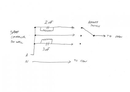
switch.jpg
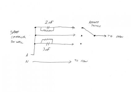
It has a 3 speed switch on the wall plate that also has a capacitor/resistor attached. It is marked MKP2+3NBL. It has 3 wires and the schematic on the side shows a 2micro Farad cap. with a 470k ohm resistor parallelled across it, and a 3 micro Farad cap. with a 470k ohm resistor parallelled across it.
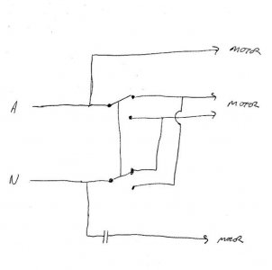
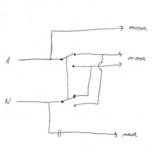
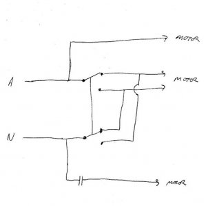
Up at the ceiling fan I have measured 240 vAC, (in Australia, that is our domestic single phase supply). On dissasmbling the motor, I have the active and neutral going to a summer/winter reversing switch, and a 1.5 micro Farad (presumably) starting capacitor, and 4 wires into the motor casing.
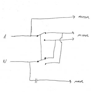
wiring1.jpg

Can anyone tell me what I should be able to measure across the various wires at the motor connections?

Cheers Phil
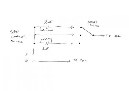
switch.jpg

switch.jpg

wiring1.jpg

wiring1.jpg
 
Check the capacitors. If they pack it in, the motor won't work.
 
The start capacitor checks out ok.
The directional switch is ok.
Of the 4 wires going in to the motor, I can measure 390 ohms across the active and neutral pair, and 280 ohm across the 2 directional switch wires pair. They show open circuit between the 2 sets of pairs. Does that sound about right?

wiring1.jpg

I have got 240 v at the active and neutral connection, (at the terminal block) but it is difficult to measure what is at the wires going to the motor because of access to the plug.
If I connect it on the bench, and I put 240v on the active and neutral pair, and 240v on the other switched pair, it should run?

Cheers Phil

wiring1.jpg

wiring1.jpg
 
Does the meter hold steady when you first connect it, or does it drift a bit before settling on your final readings? Really hard to get meaningful readings without disconnecting all the wires and testing individual parts. A working capacitor will show low resistance at first, then the resistance will go down as it charges off the meter battery. With a coil in parallel, you won't get reliable results.

I'm not sure where you were connected for the 280 ohm reading. Without disconnecting something, you always have one coil in parallel with another coil that is in series with a capacitor.
 
Mike,
I had pulled it down completely. With the hanger tube taken out and the motor cover removed there is a small 6 pin connector plug, (just like an automotive plug on the stereo or similar) to separate and then the motor windings were able to be measured without anything else connected.
However, back to the 6 pin connector............ It has a moulded hook on one half that latches onto the other half when it is PROPERLY assembled!
After testing everything and everything seeming pretty right, I thought I would give it a run on the bench. Put it all back together, and now it runs!
After thinking about that for a while, I decided, I think, that I didnt need to depress the little latch to unhook it when I was pulling it all apart. So Im thinking that the little plug vibrated apart until the connection broke, because it was never clipped together at the factory. Maybe.
Anyway, it all ended well, its back up and spinning again, and we can sleep cooler now.

thanks hawkeye and mayhem for your replies.

Cheers Phil
 
There's always a catch. It just isn't always engaged. :lmao:

Glad you got it.
 
Back
Top