First IC engine build-Own Design

Max_Power

Registered
Registered
Joined
Aug 30, 2011
Messages
48
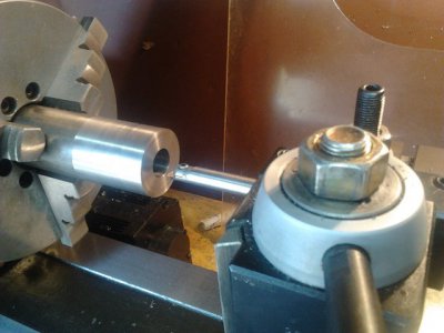
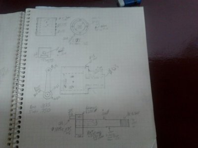
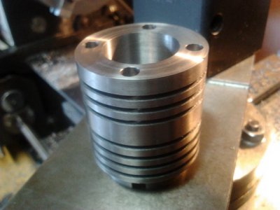
This is probably jumping in a bit too deep, But the other day after wanting to build a engine of some sort for a while, And having a hard time locating a kit or plans that really appealed to me, I decided to sketch something out and just go for it! I've always had a hard time conforming to "spec" anyway! 8) There has already been some design changes from my sketch, But I made modest accomplishment on the cylinder yesterday. The engine will be a model airplane type design , Although I'm not sure it won't end up way to heavy to put in a model. Its pretty likely I will make a glow plug head to initially get it running, But my intention is for it to be a "Diesel" (model airplane semi-diesel type with contra-piston in head) Displacement will be .45 CuIn. With a 7/8 bore and 3/4 stroke. If anyone sees anything that will be a obvious problem let me know, Although I don't want to nit-pick it to the point where I should just totally redesign and start over. I want to get it together and learn some skills...maybe itll run, maybe not? :tounge: I think I should have the cylinder completed this weekend, And can maybe get started on the piston. I'm taking a break right now and tearing apart some of my model engines to try to measure port timing events and port sizes, as I'n not certain on that yet. Thanks for looking! Todd And no, That tiny boring bar didn't work out. I changed to a 5/8 one after hearing the extreme chatter. :)

IMG_20110930_133950.jpg IMG_20110930_151300.jpg IMG_20110930_134017.jpg
 
Last edited by a moderator:
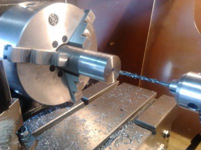
Next, I parted off the cylinder and put it under my rotary table. I really wanted to cut the fins first, But am planning on using 4 long studs going through head and cylinder and into the case....I didnt figure a drill would like cutting through a path where half the diameter of the bit was free and the other half cutting while going through the grooves. I'm sure the grooving tool will sound nasty hitting the holes, But I feel like it will be less likely to break tooling. So ,here is the cylinder on the rotary table getting the 1/8 inch holes drilled through. I'm kinda wondering right now before I tear down the setup if the studs will work? I really would like the holes slightly larger than 1/8 to fit 8-32 studs, But the next collet size I have is 3/16...And the drill chuck and bit won't fit with the RT and chuck/adaptor under it. I'm thinking now that I have the pilot holes I can set the workpeice in a vise and gain some headspace to enlarge the holes though. Todd

IMG_20111001_142548.jpg
 
Last edited by a moderator:
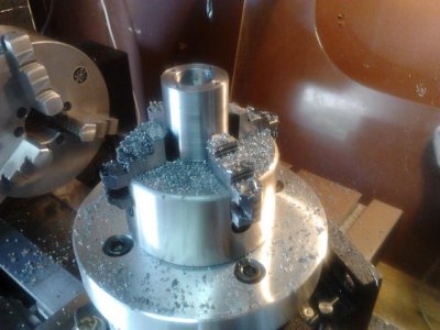
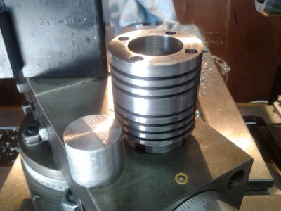
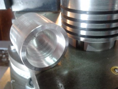
I went ahead and enlarged the thru holes to 3/16 as It just seemed like I was going to be limited in options with 1/8 holes. Then I put it back in the lathe and finned it out. The wider land in the middle will get flats milled in it to fit the intake/exhaust manifolds. I'm actually planning to make the bypass/transfer external via a brass tube from crankcase to the side of the jug, As I think it will look cool and kinda fit the styling with the large studs. Onto the piston tomorrow...I will probably put off the ports and flanges until I get a bit farther on. Todd

IMG_20111001_175109 (1).jpg
 
Last edited by a moderator:
Nice work Todd ::thumbzup::

This looks like an interesting project, I can't wait to see the next installment. :)
 
Last edited:
Thanks for the compliments guys! It will surely help keep the motivation going.

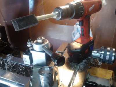
I spent a bit of time today and worked on the piston...Which is almost complete minus the wrist pin hole which will be done when I get my new set of over/under reamers from Enco Tuesday. :) I cut it to about .0005 less than the cylinder and then used my pictured homeade "hone"(coated with a ATF/white diamond paste) to polish the cylinder a bit and then worked it by hand a bit to try to get the fit loosened up.

Not sure if it will end up tight enough, But wet with solvent only it took about 5 minutes for the piston to drop through the cylinder as the bubbles leaked out of the bottom of the cylinder where it was sitting on the cross-slide.

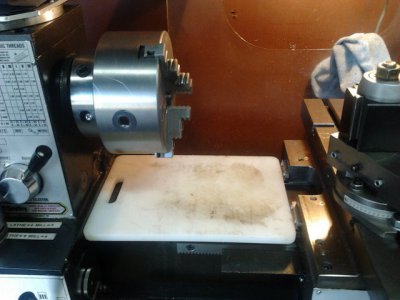
I've also added a pic of my "Tech Tip" of using a plastic cutting board to lay on the ways to prevent damage when changing out the chuck. More to come tomorrow hopefully! Todd

IMG_20111002_144616.jpg IMG_20111002_144747.jpg IMG_20111002_111721.jpg IMG_20111002_144631.jpg
 
Last edited by a moderator:
Nice work, but I hope your wife don't find out you are using her cutting board.
Paul
 
LOL...My wife is a scientist and works about 85 hours a week. I (Honestly I don't mind) do almost all of the cooking, And a pretty tasty job at that if I do say so myself(people like us are detail-oriented) ;) . If she found the cutting board she would probably say "What is this thing? Does it go to your machine??" 8) Todd
 
At least that would explain why the meatloaf has that O'de way-oil flavor. :nerd:

-Ron
 
Ok, Today's part was the wrist pin. I know, I know...thats a EASY one! Cutting the pin was a breeze, although there was a slight bit of pucker factor putting the hole in the piston.

I'm thinking on my next piston I will drill this hole first, As I'm still not sure the best way to hold small round items in v-blocks? I wasn't real impressed with my cheapy round bar center finder...I guess you get what you pay for sometimes. Part of it may be that sometimes my chuck takes a bit of fiddling to get a good runout.

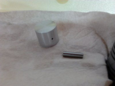
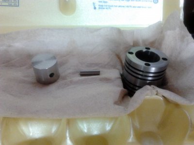
Anyway, So I parted off a piece of 3/16 O-1 drill rod about .750 long and faced the ends. Then I used a v-block in my milling vise with a round wooden dowel stuck up into the back of the piston with the clamp on the dowel to hold the piston into the block. This meant of course the drill bit would be drilling through the wood on its way through, but that was no biggie. I spotted and drilled the hole at 9/64 about .850 through the .875 piston..so that the drill point just barely punched through. Then I ran a .1885 (.001 over 3/16) reamer through stopping a bit short of the far side as well.

My plan is for the wrist pin to be full floating, slides in through one side but can't come out the other, Then a small delrin disk will be put in the side of the piston the pin went into to keep the pin off of the cylinder wall. I'm pretty sure the wall won't mind the "button" rubbing on it a bit. The hole in the far side was deburred by hand spinning a 1/4 drill bit in it from the outside, and should be enough to let a little lube in?

I lopped off a 2.5x2.5x5 chunk of 6061 on the band saw for the crankcase last night, But I'm assuming next will be the connecting rod. :nerd: Thanks for looking! Todd

IMG_20111004_173158.jpg IMG_20111004_173212.jpg
 
Last edited by a moderator:
The piston "button" idea should work fine. They use the same idea in Nitromethane drag racing engines that produce well in excess of 7000 (thats right 7 thousand estimated) horsepower.
 
Last edited:
Back
Top