Last weekend I did a repair that was quite unusual (at least for me). One doesn't see much stuff like this online so I decided to post it here thinking members may find it interesting.
There is this tiny computer controlled (4cmx12cm or roughly 1.5'' by 5'') hydraulic pump that pumps oil to operate a clutch that engages an all wheel drive on my car (it is a vw golf 2005, the awd unit is called haldex). That little device is seriously under engineered considering many (including very expensive) cars use it. The electric motor in it fails after some use and replacements are rather expensive (for an old car). So I was hoping my hobby machine shop will help me in fixing it and I wasn't disappointed.
This is the pump assembly:
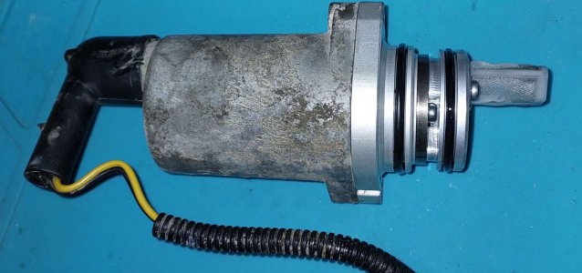
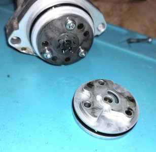
This is the actual pump mechanism. The shaft is 4mm or 0.16in only.
And this is the offending electric motor:
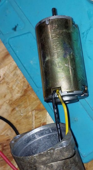
12V, 35*60mm motor. (about 1.25 by a bit over 2 in).
And that's how it looked inside:
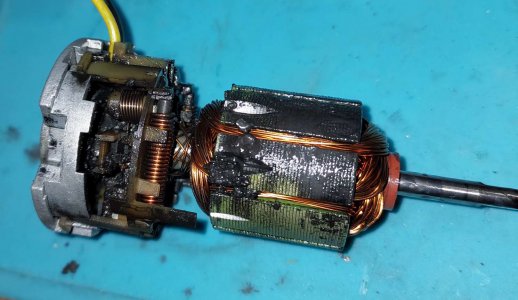
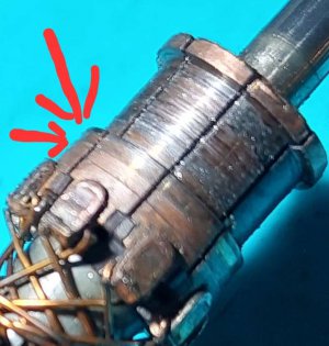
Oh my, carbon crud everywhere, brushes gone and after making a custom puller for the top bearing and cleaning this is how worn the commutator was:
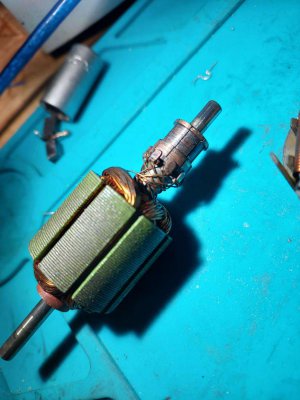
It is not that visible on the photo, but the copper worn completely away on few sections showing the isolator underneath. Where it remained it was tinfoil thickness.
At this stage any "normal person" would throw the whole lot into a junk bin and buy new, or maybe order a new commutator if possible. But as it was a weekend and I thought I can fix it I gave it a go.
First I made a socket to support the top of the shaft while turning and I turned down thd remaining copper on the top and I notched the bottom with a file:
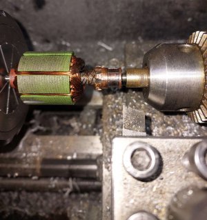
After cleaning it looked like this:
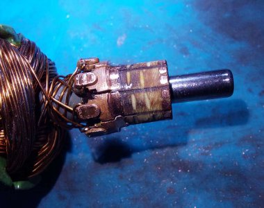
Then I made a brass ring (I had no copper round, the change in conductivity is negligible). I glued it with two part high temp epoxy and I soldered it to the bits of the previous commutator. I then turned it down to size on my mini lathe:
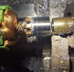
Then it was sanded and polished in preparation for slitting in this setup:
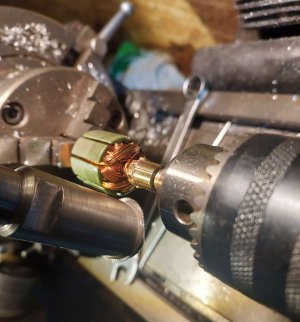
This was on my Chinese mini mill using a 25mm x 0.3mm 80 tooth slitting saw. That's 1in diameter, 11 thou thickness in English units.
After additional sanding and polishing to remove burrs and cleaning it looked like this:
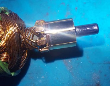
Now I only had to make new brushes using a small file and spare brushes I had previously bought for my angle grinders and after some bench testing the little motor was reassembled in the pump and the pump was reinstalled into the car and it works fine
So I saved a couple hundred $ and spent 3 days in the shop (and under the car)
There is this tiny computer controlled (4cmx12cm or roughly 1.5'' by 5'') hydraulic pump that pumps oil to operate a clutch that engages an all wheel drive on my car (it is a vw golf 2005, the awd unit is called haldex). That little device is seriously under engineered considering many (including very expensive) cars use it. The electric motor in it fails after some use and replacements are rather expensive (for an old car). So I was hoping my hobby machine shop will help me in fixing it and I wasn't disappointed.
This is the pump assembly:

This is the actual pump mechanism. The shaft is 4mm or 0.16in only.

And this is the offending electric motor:

12V, 35*60mm motor. (about 1.25 by a bit over 2 in).
And that's how it looked inside:

Oh my, carbon crud everywhere, brushes gone and after making a custom puller for the top bearing and cleaning this is how worn the commutator was:

It is not that visible on the photo, but the copper worn completely away on few sections showing the isolator underneath. Where it remained it was tinfoil thickness.
At this stage any "normal person" would throw the whole lot into a junk bin and buy new, or maybe order a new commutator if possible. But as it was a weekend and I thought I can fix it I gave it a go.
First I made a socket to support the top of the shaft while turning and I turned down thd remaining copper on the top and I notched the bottom with a file:

After cleaning it looked like this:

Then I made a brass ring (I had no copper round, the change in conductivity is negligible). I glued it with two part high temp epoxy and I soldered it to the bits of the previous commutator. I then turned it down to size on my mini lathe:

Then it was sanded and polished in preparation for slitting in this setup:

This was on my Chinese mini mill using a 25mm x 0.3mm 80 tooth slitting saw. That's 1in diameter, 11 thou thickness in English units.
After additional sanding and polishing to remove burrs and cleaning it looked like this:

Now I only had to make new brushes using a small file and spare brushes I had previously bought for my angle grinders and after some bench testing the little motor was reassembled in the pump and the pump was reinstalled into the car and it works fine
So I saved a couple hundred $ and spent 3 days in the shop (and under the car)


