- Joined
- Aug 3, 2017
- Messages
- 2,437
On past projects, I've noticed I get significant tailstock 'droop' that goes away when I tighten the tailstock. Typically isn't a problem, since my through-holes are usually pretty sizable, so I use a pretty big center. Unfortunately, the steam engine project I just finished (PM Research #3) showed me that this isn't the case! I was drilling holes too small to do anything more than dimpling! I was having to hold the tailstock lock and turn the wheel against it to get a centered dimple.
SO, I looked at the parts diagram for my lathe! I noticed that there is a key under the front of the tailstock extendy piece! SO, I pulled the tailstock apart and noticed that not only does it have quite a bit of gap, someone has already 'flipped' it around once! I was able to find that it was at .369" (.359" at the other!) at the 'thick' side, but the gap in between the tailstock and the extendy-piece was .382"!
I considered shimming it, but the fact that it was so uneven makes me think that this is perhaps a bad idea. SO, I chose to make a new one! My order of operations isn't great (IMO), but I got the piece done and the one critical dimension (height) pretty darn close.
Here is the 'socket' that the extendy-bit goes into. You can see the keyway with a hole in the bottom of it. Right behind that is the 'clamping' mechanism. The bore itself is kinda scored, but hey, its 80 years old!

Here's the old piece. One thing of interest is that the previous person seems to have filed the sides down. I didn't find that necessary. You can also see the 'rough' shape that the top contact surface is in!


And how it goes into the extendy-bit:

And here is the victim! i have a piece of class 40 cast iron I bought for a gib project that should be perfect.

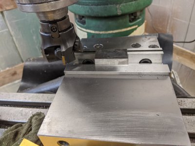
Step one was squaring it up in the mill. I thought about cutting it 'long way', in order to get the 'thickness' but I didn't have a good way of doing that. My bandsaw doesn't have a horizontal mode, and I couldn't clamp it in a way that would let me cut it in half. SO, I ended up wasting 2/3 of the piece! I attempted to get the 'width' component (left to right) all set, as well as the length(headstock to tail). I'll leave the height for last.

I realized as I hogged out the material that I haven't used my surface grinder since I got it on the RPC! SO, I decided to tune in the width/thickness with the surface grinder! I was REALLY happy with the finish, it did a way better job than the VFD.


Then, I popped it in the 4 jaw and cut the sticky-out-bit that indexes in the bottom of the tailstock tube. This is where I messed up. That + the flat that the lathe creates SHOULD have been my index surfaces and I should have ground based on those. I ended up not getting it set up perfectly in the lathe, so it is tilted ever so slightly (I could see it due to the 'uncut' part on the side of the post. I was surprisingly able to get it to fit in the slot perfectly anyway! Another issue is that the 4 jaw chuck marred the finish (I didn't think about it), so I had to file the burr that raised down.

And the nearly finished part! This is before I fine tuned the height in.
I would Love to say that I got this just right, but I made a math error when trimming it down in the mill. I had intended on cleaning it up in the surface grinder, but for some reason I took too much off in the mill. I ended up at .379, so I didn't want to take any more. I touched the top with a file for deburring purposes. I did a test fit (expecting it to either be disappointingly loose and encouraging me to start again tomorrow, or not fit at all, and leave me a thou to take off in the surface grinder!), but it actually fit just right! It is perhaps SLIGHTLY too tight (I cannot get the very end of the extendy-bit out anymore, I suspect I'd have to take the handle off and tap it out from the other side), but when turning the wheel it is as easy as ever.
I measured the droop, what used to be about 12 thou is now down to 3 thou at 7 inches of extension. I'm happy with that")
SO, I looked at the parts diagram for my lathe! I noticed that there is a key under the front of the tailstock extendy piece! SO, I pulled the tailstock apart and noticed that not only does it have quite a bit of gap, someone has already 'flipped' it around once! I was able to find that it was at .369" (.359" at the other!) at the 'thick' side, but the gap in between the tailstock and the extendy-piece was .382"!
I considered shimming it, but the fact that it was so uneven makes me think that this is perhaps a bad idea. SO, I chose to make a new one! My order of operations isn't great (IMO), but I got the piece done and the one critical dimension (height) pretty darn close.
Here is the 'socket' that the extendy-bit goes into. You can see the keyway with a hole in the bottom of it. Right behind that is the 'clamping' mechanism. The bore itself is kinda scored, but hey, its 80 years old!
Here's the old piece. One thing of interest is that the previous person seems to have filed the sides down. I didn't find that necessary. You can also see the 'rough' shape that the top contact surface is in!
And how it goes into the extendy-bit:
And here is the victim! i have a piece of class 40 cast iron I bought for a gib project that should be perfect.
Step one was squaring it up in the mill. I thought about cutting it 'long way', in order to get the 'thickness' but I didn't have a good way of doing that. My bandsaw doesn't have a horizontal mode, and I couldn't clamp it in a way that would let me cut it in half. SO, I ended up wasting 2/3 of the piece! I attempted to get the 'width' component (left to right) all set, as well as the length(headstock to tail). I'll leave the height for last.
I realized as I hogged out the material that I haven't used my surface grinder since I got it on the RPC! SO, I decided to tune in the width/thickness with the surface grinder! I was REALLY happy with the finish, it did a way better job than the VFD.
Then, I popped it in the 4 jaw and cut the sticky-out-bit that indexes in the bottom of the tailstock tube. This is where I messed up. That + the flat that the lathe creates SHOULD have been my index surfaces and I should have ground based on those. I ended up not getting it set up perfectly in the lathe, so it is tilted ever so slightly (I could see it due to the 'uncut' part on the side of the post. I was surprisingly able to get it to fit in the slot perfectly anyway! Another issue is that the 4 jaw chuck marred the finish (I didn't think about it), so I had to file the burr that raised down.
And the nearly finished part! This is before I fine tuned the height in.
I would Love to say that I got this just right, but I made a math error when trimming it down in the mill. I had intended on cleaning it up in the surface grinder, but for some reason I took too much off in the mill. I ended up at .379, so I didn't want to take any more. I touched the top with a file for deburring purposes. I did a test fit (expecting it to either be disappointingly loose and encouraging me to start again tomorrow, or not fit at all, and leave me a thou to take off in the surface grinder!), but it actually fit just right! It is perhaps SLIGHTLY too tight (I cannot get the very end of the extendy-bit out anymore, I suspect I'd have to take the handle off and tap it out from the other side), but when turning the wheel it is as easy as ever.
I measured the droop, what used to be about 12 thou is now down to 3 thou at 7 inches of extension. I'm happy with that