-
Welcome back Guest! Did you know you can mentor other members here at H-M? If not, please check out our Relaunch of Hobby Machinist Mentoring Program!
You are using an out of date browser. It may not display this or other websites correctly.
You should upgrade or use an alternative browser.
You should upgrade or use an alternative browser.
Flat Twin
- Thread starter rdean
- Start date
- Joined
- Mar 8, 2015
- Messages
- 305
Should work
- Joined
- Feb 2, 2014
- Messages
- 1,054
I have finally made a decision on the ignition system, I am going to try to make a distributor.
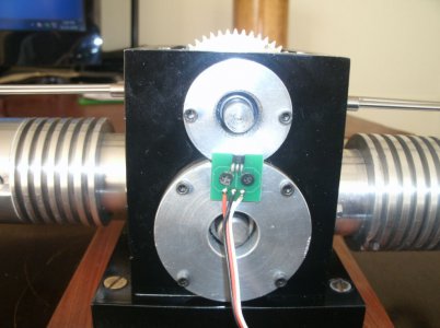
This picture shows the hall effect sensor mounted on the rear main bearing cap.
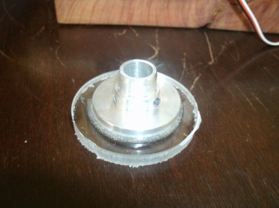
And this is my attempt to make a rotor.
Plexiglass ring epoxied to an aluminum hub that is mounted on the cam shaft. This side of the aluminum hub will have two magnets set 180 degrees apart so that the ignition module will fire every revolution of the engine but just to a different plug each time. The hub is adjustable on the cam shaft for ignition timing
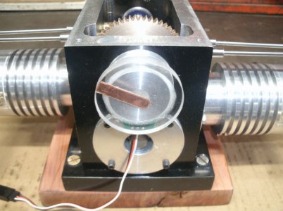
A 1/4" wide copper strip was inlaid into the face of the plexiglass disk.
The wire from the ignition module will come into the center of the ring and each plug wire will be set toward the outside and 180 degree apart.
Still thinking about how I want to make the cap for the high voltage wires.
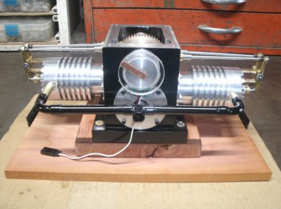
Soldered and painted the intake manifold what a fussy job.
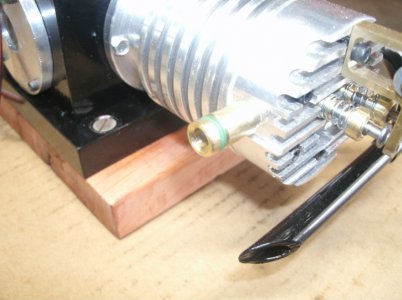
I wanted the intake manifold and the exhaust pipes removable for disassembly so I used o-rings for both.
Here is one for the intake manifold.
Thanks for looking
Ray
This picture shows the hall effect sensor mounted on the rear main bearing cap.

And this is my attempt to make a rotor.
Plexiglass ring epoxied to an aluminum hub that is mounted on the cam shaft. This side of the aluminum hub will have two magnets set 180 degrees apart so that the ignition module will fire every revolution of the engine but just to a different plug each time. The hub is adjustable on the cam shaft for ignition timing

A 1/4" wide copper strip was inlaid into the face of the plexiglass disk.
The wire from the ignition module will come into the center of the ring and each plug wire will be set toward the outside and 180 degree apart.
Still thinking about how I want to make the cap for the high voltage wires.

Soldered and painted the intake manifold what a fussy job.

I wanted the intake manifold and the exhaust pipes removable for disassembly so I used o-rings for both.
Here is one for the intake manifold.

Thanks for looking
Ray
- Joined
- Mar 8, 2015
- Messages
- 305
Wow! You have really been busy.
- Joined
- Feb 2, 2014
- Messages
- 1,054
I had a set back yesterday after I installed the magnets on the rotor. While testing for a spark I found that only one of the magnets triggered the ignition module to fire but the other had no effect. I thought maybe I had messed up and installed one of the magnets upside down so I turned the offender over. That magnet started working but the other one that had worked before stopped. In order to turn the disk more easily by hand I removed the 6/32 set screw that held the rotor on the cam shaft. Now both magnets worked but one did not fire the sensor at the right time. Removing the set screw was the only think I did and then it hit me. Maybe the magnets were fighting each other because they were mounted too close together.
Today I made a new larger rotor with the magnets spaced about 2" apart and now it works like it should.
I still have to make a new plexiglass cover for the rotor arm and a new copper wiper.
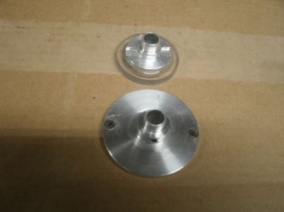
The old and the new.
I had to move the hall sensor and shim it out with a brass spacer in order to place it properly under the magnets..
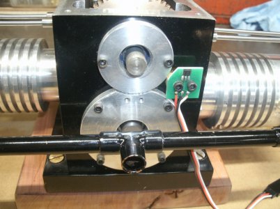
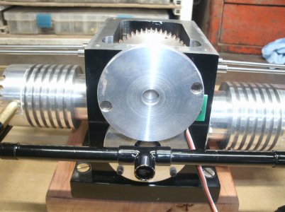
The rotor installed on the engine.
Thanks for looking
Ray
Today I made a new larger rotor with the magnets spaced about 2" apart and now it works like it should.
I still have to make a new plexiglass cover for the rotor arm and a new copper wiper.
The old and the new.

I had to move the hall sensor and shim it out with a brass spacer in order to place it properly under the magnets..

The rotor installed on the engine.

Thanks for looking
Ray
- Joined
- Nov 26, 2017
- Messages
- 1,515
Some amazing work. Very well thought out. I know you are not following any plans, so your trial and error is most like an original inventor. My hat is off to you. So much to take into account on something like this.
- Joined
- Feb 2, 2014
- Messages
- 1,054
Papa Charlie thank you very much for your comment and for following my build. Since Covid started I have surprised myself with the complexity of the parts I have made and also the quality of my machining. I enjoy trouble shooting problems and figuring out how I can make something work with what I have and know.
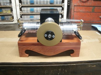
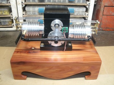
The last few days when I have had to wait for a process to finish or paint to dry I have been working on the wood base for the engine. Today it is almost finished so I mounted the engine and hooked up some wiring.
It is built from cedar and similar in design to the one for my Royal Blue engine. The finish is Johnson's past wax over a clear spray.
Front view
Rear view
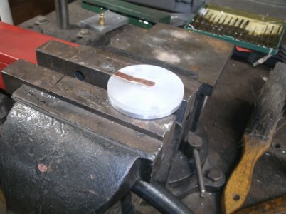
This is the new rotor assembly with the insulator, the magnets and the wipe arm.
My version of a distributor.
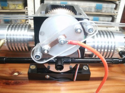
I am waiting on some high voltage wire for the two spark plugs but right now the design looks promising.
I decided not to build a carburetor but instead I purchased a SH .18 that has all the jets, needles, and adjustable throttle that I want. It was recommended by another builder of a similar sized engine and he really likes it. The carb was made for the model nitro car and truck people but I think it will work here also.
Thanks for looking
Ray
The last few days when I have had to wait for a process to finish or paint to dry I have been working on the wood base for the engine. Today it is almost finished so I mounted the engine and hooked up some wiring.
It is built from cedar and similar in design to the one for my Royal Blue engine. The finish is Johnson's past wax over a clear spray.
Front view

Rear view

This is the new rotor assembly with the insulator, the magnets and the wipe arm.

My version of a distributor.

I am waiting on some high voltage wire for the two spark plugs but right now the design looks promising.
I decided not to build a carburetor but instead I purchased a SH .18 that has all the jets, needles, and adjustable throttle that I want. It was recommended by another builder of a similar sized engine and he really likes it. The carb was made for the model nitro car and truck people but I think it will work here also.
Thanks for looking
Ray
- Joined
- Feb 2, 2014
- Messages
- 1,054
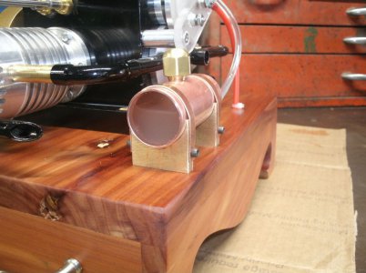
All of the gas tanks that I have built for other models have had one major flaw. It is very hard to tell just how much gas is in the tank.
This gas tank would be different.
I made it with plexiglass ends. Shown here being leak tested on it's brass stands.
And an overview of the rear of the engine.
What do you think?
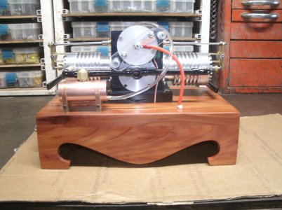
I also put some handles on each end of the base so it would be safer moving it around.
Thanks for looking
Ray
This gas tank would be different.
I made it with plexiglass ends. Shown here being leak tested on it's brass stands.

And an overview of the rear of the engine.
What do you think?

I also put some handles on each end of the base so it would be safer moving it around.
Thanks for looking
Ray

