Flat Twin

rdean

Active User
H-M Supporter Gold Member
Joined
Feb 2, 2014
Messages
1,056
I have built three different hit-miss engines since this covid thing started mainly to have something to keep me busy. When I started the first build, a Kerzel from plans, I thought maybe I would end up with a display model that didn't look too bad but did not run. Well that didn't happen as all three of my models run very nicely and my building skills have improved with each engine.
Now I am ready for something more complicated and the Upshur Twin caught my eye. I acquired a set of plans but I soon realized that I didn't want to build the engine the way the author had so here is my take on my flat twin.
The specifications of what I wanted for my engine are.
1" Piston
1" Stroke
Ball bearing Crank shaft mains
Ball bearing Cam shaft
One piece crank case
Electronic ignition

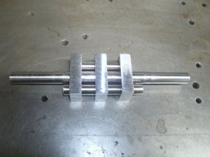
I started with the crank shaft making it the same way I had done on the other models but I soon found out that a two throw crank shaft is immensely more complimented that a single throw crank. After several failed attempts I decided to try this method.
GEDC4714s.JPG
It is made of six pieces, three shafts and three bars. These were assembled with a close fit and red locktite and left over night.
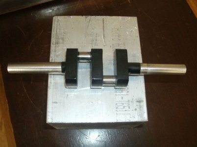
Next day the shafts were further secured using 1/8" pins through the bars and shafts. Next was to cut out the bits I didn't want and do some shaping of the bar ends and a coat of paint.
The crank ended up very true and it even looks nice.
GEDC4716s.jpg

Next up is the crank case.
Thanks for looking
Ray
 
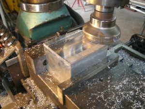
I have a block of aluminum about 4 X 3 1/2 X 3 that I will be using for the crank case so I squared it up on all sides.
GEDC4720s.jpg

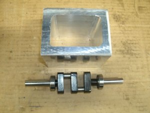
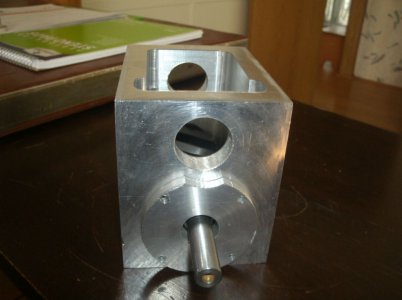
I then hollowed out the inside of the block leaving 1/2" walls all around. The finished product turned out nice but what a pile of chips and several hours milling. I didn't have an end mill long enough so I had to cut from the both sides to the middle.
GEDC4724s.jpg

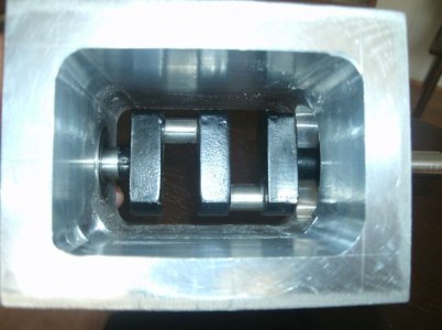
It looks like the crank will fit inside and hopefully have enough room for the throw of the connecting rods.

Thanks for looking
Ray
 
Nice work. Are you going to balance the crankshaft?
 
I don't have the equipment or knowledge to balance the crank shaft.
Wouldn't you have to have the connecting rods, pistons, and all the other moving bits included in the balancing job to be accurate?

Ray
 
You can set the central shaft between centers, allowing the shaft to turn freely, or on rollers. If the shaft is balanced, it should stay where ever you rotate it to. One side offsetting the other. If one drops then it is heavier than the other and you could balance taking a small drill and remove some from the heavy side.

You can use some copper wire to wrap around the light side to identify the amount of weight that will either need to be added or reduced, depending on how you want to adjust the weight. If you choose to reduce, then take the weight divided by the density of the material and that will give you the volume to remove. Easy enough to figure how deep of a hole to drill based on the diameter of the drill bit.

I would not include the bearings as they are supported by the crankcase. Just the crankshaft.

Then for the piston assemblies, use a very accurate scale to make sure they both weigh the same, removing material form each component to make them the same.

Just like when you blue print and balance a racing engine. But that includes balancing the volume of the combustion chambers as well.
 
Last edited:
I will have to give that balancing a try.

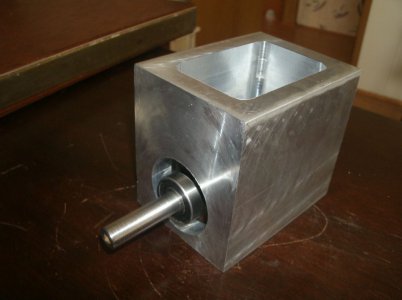
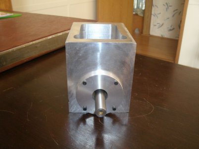
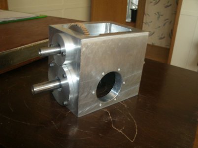
Drilled the large hole for the crankshaft and installed a bearing for the other end.
I will probably make the other end the flywheel end.
GEDC4727s.jpg

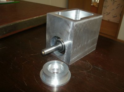
Made a bearing cap for this end and screwed it in place.
GEDC4733s.jpg
GEDC4737s.jpg


See it does fit inside.
GEDC4730s.jpg


Now where to put the cam shaft so that the cam lobes have enough clearance to miss the connecting rod ends.
This was an issue I had thought about for several days because the timing gears have to large enough to connect to the cam and the crank. If they are too small there won't be enough clearance and if too large they won't fit inside the crank case.
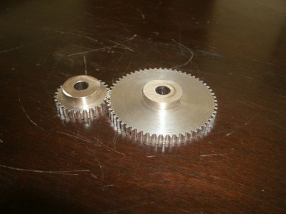
These are what I decided on for gears a 29 tooth and a 58 tooth Module 1 set.
GEDC4744s.jpg


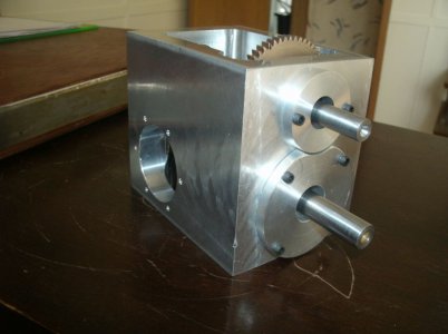
I screwed upon the first set so I had to make another . These will give me enough height for the cam but the large gear doesn't fit inside the crankcase. I f you look two pictures up you can see how I remedied this by cutting into the side walls. I will have a cover with a trough cut into the bottom of it to cover the part of the large gear that sticks out the top of the crank case.

Thanks for looking
Ray
 
Nice work. A couple of questions and comment:

1) Is there sufficient clearance for the piston rods? It is hard to tell from the picture as I have no frame of reference.
2) Will this be a flooded crankcase, if so, will you install seals on the crankshaft?
3) Really nice way to work out the issue with the gear. I love the creativity of the members here.
 
Along with the cam shaft fitting I was concerned about enough room for the connecting rods. I made a crude drawing to see if I would have any interference to the connecting rods and it turned out they were very close to hitting the inside of the crank case as their angle changed. To make sure there would not be a problem I extended the cylinders into the sidewalls by 1/4" and this allowed me to make the cylinder openings 1.600 in diameter all the way through the wall thickness. Now there is plenty of room for the rods.
The bearings are all rubber sealed or 2RS type and I will have the crank case well vented so hopefully it won't be a problem we will just have to see.

Bored the holes for the cam shaft bearings.
GEDC4750s.jpg

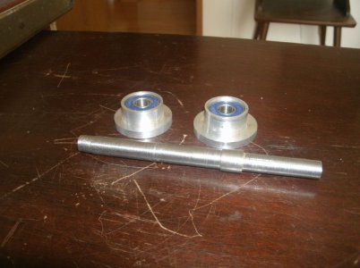
This is the cam shaft and the bearing blocks.
GEDC4748s.jpg

I had to cut away part of the crank shaft bearing block in order for the cam bearing block to fit. I also bored the two cylinder locating holes and spotted for the cylinder mounting bolt holes.
GEDC4752s.jpg
GEDC4753s.jpg

Thanks for looking

Ray
 
Tapped the holes for the cylinder bolts in the crank case and started on the cylinders.
I really messed up on this one do you see where I went wrong?
GEDC4757s.jpg

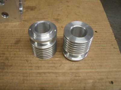
I parted some cooling fins at 0.200 deep in the cylinders and it went well.
And here are the cylinders done except for the inner liners and head bolts holes.
GEDC4760s.jpg

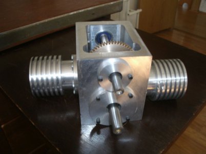
It is starting to look like an engine.
GEDC4762s.jpg

Thanks for looking
Ray
 
Missing the register step in the cylinder profile.

This looks fantastic. What are you using for the liners?
 
Back
Top