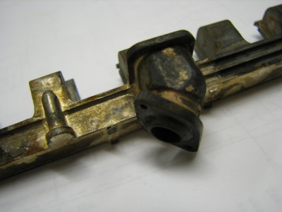
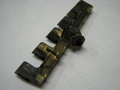
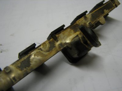
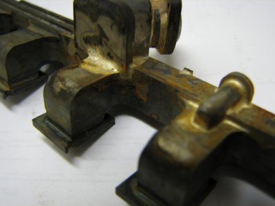
Ford 300 inline six cylinder engine

gbritnell

Active User
Registered
Joined
Mar 22, 2013
Messages
215
Gentlemen,

One of my last threads was on making helical gears for the above mentioned project. I have been working on it since late last summer and am getting close to finishing. I have done a complete build thread on another forum with partial builds on a couple more so the time involved in total documentation on multiple forums is very time consuming.

Here's a little background on the project. I have engines in quite a few cylinder configurations, singles, twin, 4, 5, and 8. I wanted to build a 6 cylinder engine somewhat based on my 4 cylinder OHV engine but with 6 cylinders. I started with the drawings I had made for the 4 and set about making the necessary changes. Shortly into the project I realized I didn't want another generic looking engine so having worked for Ford most of my life I decided to emulate the venerable 300 cu. in. inline six. It was at this point in the design that the only thing I gleaned from the 4 drawings were the bore and stoke, almost everything else changed.

The engine is completely scratch built, the block from aluminum, the head from iron, the crank and cam from steel, the rods from bronze and the many other parts from these metals. The bore and stroke are .75 x .875. This engine will have complete cooling through the block and head. It will be a splash oiling system and have an electronic Hall trigger ignition.

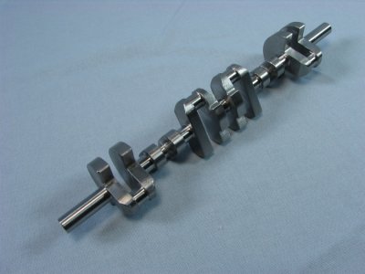
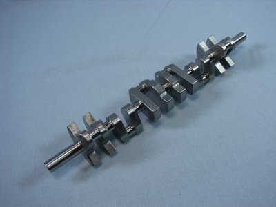
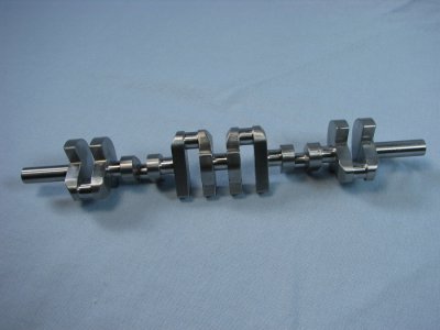
The cranks is made from 1144 stressproof steel. The configuration looks different form most cranks but this was copied from the full sized crank. If worse comes to worse in regard to balance I can always remove the extra stock from the counterweight area.

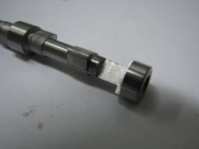
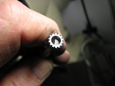
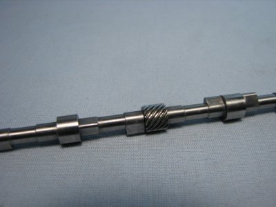
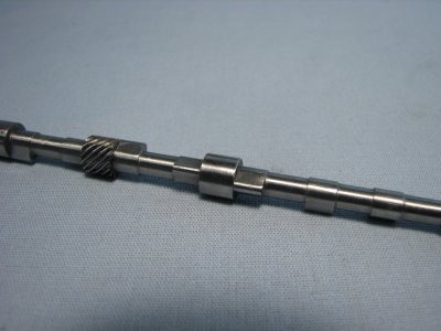
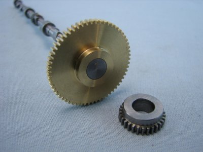
The cam is made from W-1 drill rod and left unhardened. The lifters will be hardened and polished. In trying to follow the full sized engine the distributor needed to be placed mid block so that was the need for the helical gear set. The cam blanks were milled with matching flats on the inner ends and upon assembly were pressed and Loctited in place. The cam was set into a fixture for alignment until the Loctite set although the fit of the tangs and the gear held it almost perfectly in alignment.

gbritnell
CRANK FIN 1.JPG CRANK FIN 3.JPG CRANK FIN 4.JPG IMG_0810.JPG IMG_0823.JPG IMG_0900.JPG IMG_0903.JPG IMG_0931.JPG
 
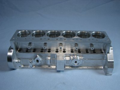
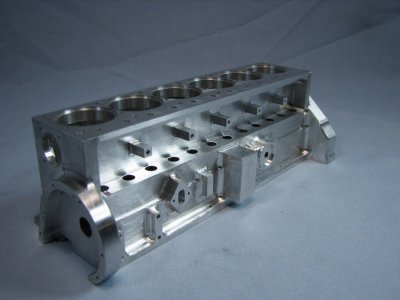
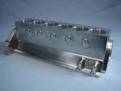
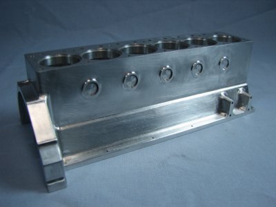
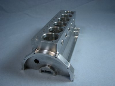
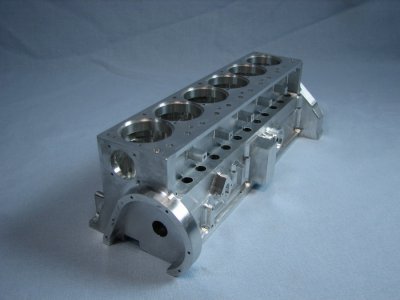
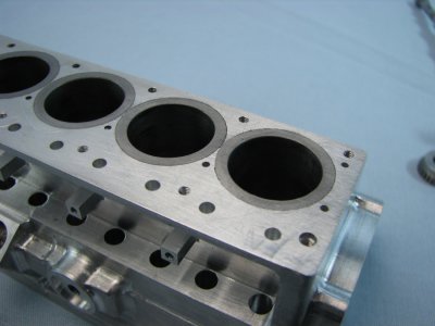
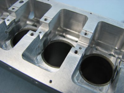
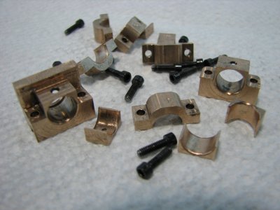
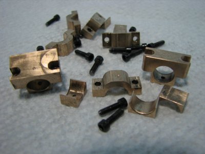
Next up is the block. This was machined from 6061 aluminum. The water jacket area was cut out using a modified Woodruff key cutter to undercut the head deck area. A step off chart was made to move the cutter to several different points within the bore hole to remove the stock. This process was repeated numerous times per bore hole to step down to the proper depth. Iron sleeves were turned to 2 different diameters on the outside, smaller on the bottom to facilitate pressing in place. The inner bore was left about .0015 small so that it could be honed after pressing. On this engine I decided to use a somewhat different approach in regard to the main bearings. Rather than make caps with inserts the bearings were cut rectangular with mounting flanges from bearing bronze. The reason behind this was due to my experiences trying to line bore small diameters and the inevitable runout that occurs. This way the bearing slot could be milled square in a convention setup and the bearings milled and reamed with a fixture to insure accuracy. The front and rear mains are one piece while the inner bearings are split to fit over the journals.
gbritnell
IMG_0121.JPG IMG_0127.JPG IMG_0130.JPG IMG_0133.JPG IMG_0136.JPG IMG_0139.JPG IMG_0934.JPG IMG_0937.JPG IMG_0940.JPG IMG_0941.JPG
 
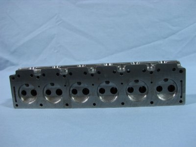
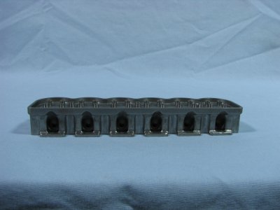
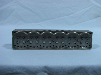
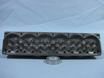
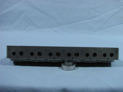
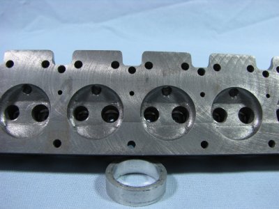
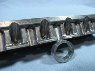
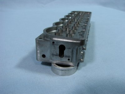
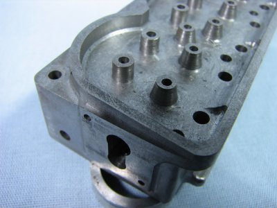
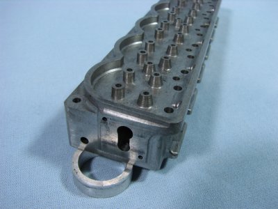
The next major part was the cylinder head. This was made from ductile iron which can be purchased as Durabar or Schedule 40 iron. It is a very fine grained iron that machines great leaving nice sharp corners and edges. I prefer to use iron that way the valve seats and guides can be machined right into the head without the additional problems that valve pocket inserts sometimes cause. I don't cut the seats while machining preferring to use a home-made seat cutter to align with the valve guide. This way if any of the pocketing is a little off the cutter will clean up the seat true to the guide. Much as in full sized practice. In following the design of the Ford 300 head the spark plugs are located on the pushrod side of the head. This only allows so much space to get the plugs in so for this engine they will be made with 8-36 threads and .219 hexes. For the water passages holes were drilled completely though the head and then plugged at the ends. The holes from the head face were then drilled up into these passages. At the front of the head a larger opening was made to accommodate the water outlet fitting.
gbritnell
head a.jpg head b.jpg head c.jpg head d.jpg head e.jpg head f.jpg head g.jpg head h.jpg head i.jpg head j.jpg head k.jpg
 
Nice work you've done it look almost like the real thing. I remember that engine well I had a 240 six in my 72 F100 dammed strong engine and ran very well to. Keep up the good work I'll have to follow this, did you make prints if so how much to get a set?

Thanks,
Todd
 
I have most of the drawings finished. As I make the parts I go back and make the necessary changes to the drawings. I should have them complete and corrected by the end of March.
gbritnell
 
Wow that's nice. You just made me realize how much I don't know.lol
 
I love the I6. It has the stroke of a diesel and makes for a really clean engine compartment. Excellent work (at the risk of understatement).
 
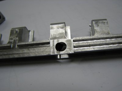
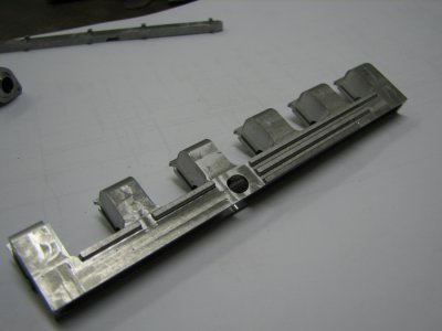
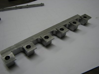
The intake and exhaust manifolds were next. The intake was a fairly simple machining exercise, take a piece of aluminum, drill and ream it from both ends then cut out the runner and flange areas. The through hole would be end plugged and finished later.

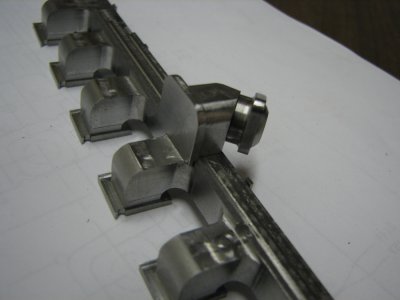
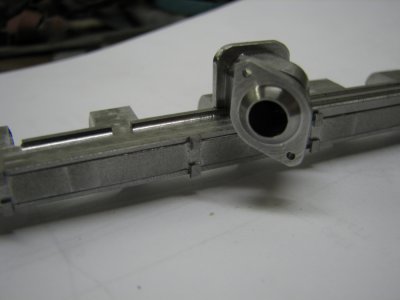
The exhaust on the other hand had quite a few design issues to resolve. Here again a simpler design would have worked much easier but in keeping with trying to replicate the full sized engine I wanted to make it as close as possible. The first thing was how to get the porting from horizontal to vertical to horizontal with a 90 degree bend then vertical again. This would call for a fabrication with some welding or silver soldering depending on the material used. My choices were brass and steel with the former much easier to machine and then possibly having it plated with nickel but I have never used brass for this type of manifold so I went with steel.

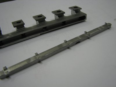
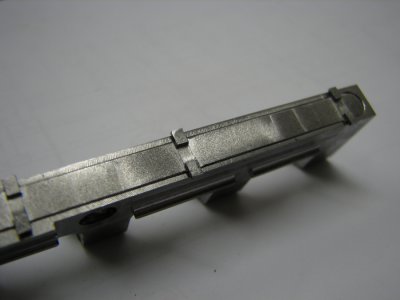
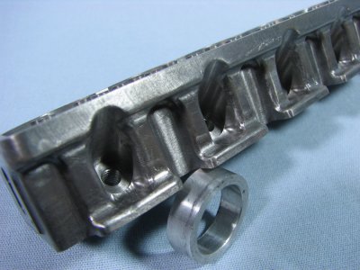
The first operation was to drill the ports from the head side followed by drilling from the bottom of the main runner. This would give my my first right angle bend. The next step was to mill a trough with a ball mill along the bottom of the runner giving me my second passage. With the drilling finished I started profiling the manifold. As the full sized piece is a casting I tried to replicate some of the shapes including the ribbing along the face. The hardest step was making a custom cutter to undercut the mounting flange where it joins the main runner. I made a cutter from drill rod that was the proper thickness and had a large radius on on corner to give me the proper inside shape.

gbritnell
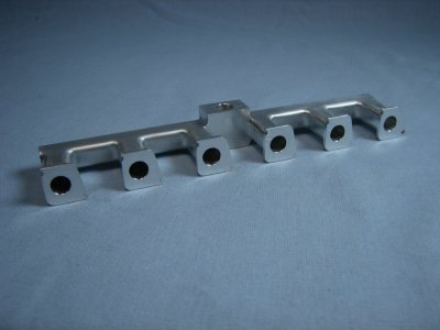
- - - Updated - - -

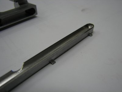
To cap over the slot I had made in the bottom of the main runner I cut a piece of stock with a matching radius that would fit up inside the runner. To hold it in place I would need to use some small clamps when silver soldering so I left small tabs along the length to keep it as flush as possible.

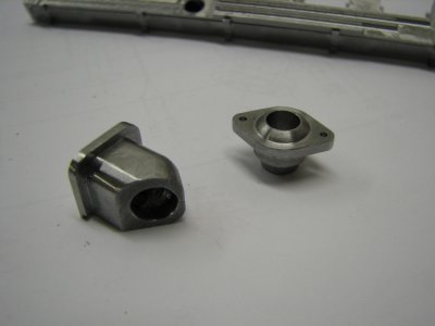
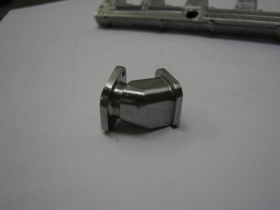
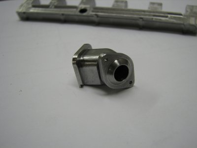
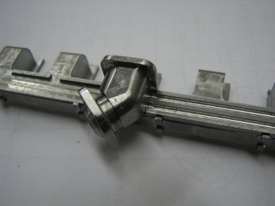
I wanted to do all the soldering at one time so prior to this operation I had to fabricate the outlet box and flange. This would give my the final right angle bend. The collector box was made as was the outlet flange and these 2 pieces were soldered together with a higher temperature silver solder.

gbritnell
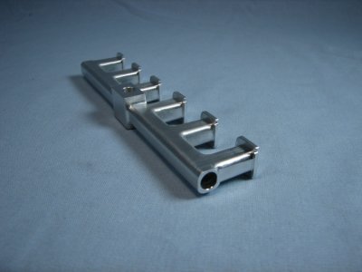
- - - Updated - - -

I apologize for the stack up of pictures but I didn't realize that when I replied to the thread that it would gang up the reply with the previous post.

Anyway, once the parts were ready for soldering everything was cleaned up, fluxed and and clamped together. I tried to heat the whole piece evenly to prevent any warping.

gbritnell
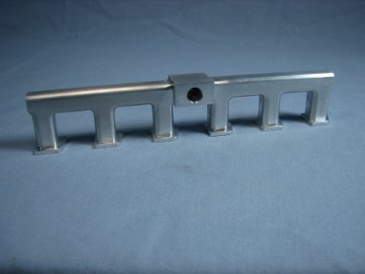
IMG_0601.JPG IMG_0604.JPG IMG_0610.JPG IMG_0613.JPG IMG_0616.JPG IMG_0619.JPG IMG_0624.JPG IMG_0625.JPG IMG_0642.JPG IMG_0646.JPG IMG_0651.JPG IMG_0652.JPG IMG_0655.JPG IMG_0658.JPG IMG_0628.JPG IMG_0631.JPG IMG_0663.JPG IMG_0666.JPG IMG_0667.JPG IMG_0670.JPG
 
"jawdrop:Wow! I'm pretty speechless. That's an incredible undertaking. I can't even imagine the amount of hours that goes into something like this. Besides all the skill involved. AMAZING!
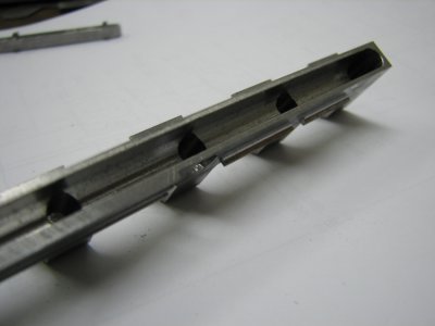
 
George, that is a fantastic project, and I wish to thank you for posting it here! Excellent work!
 
Back
Top