- Joined
- Mar 22, 2013
- Messages
- 215
Gentlemen,
I would like to present to you the ongoing project that I'm involved with.
In the 70's while working for Ford Motor as a metal patternmaker I started to build a 3/10 scale 302 Ford v-8 engine. There was talk about discontinuing the engine and I thought that while information for it was still available I would start the project not knowing if or when it would ever get finished. I had already built a multi-cylinder I.C. engine so I had some knowledge of what was needed as far as design and machining.
Being as it was in the 70's there weren't any of today's wonderful digital cameras to document the build. I did take some film pictures and though the years with tear downs and such I have taken other pictures to show some of the detail.
Over the years when I would attend model engineering and antique engine shows I would inevitably be asked "when are you going to build the rest of the car?" I never gave it much thought until a few years ago when my winter project became a Borg-Warner T-5 transmission, also in 1/3 scale. This winter's project is the modeling of a fully functional Ford 9" differential. I hope that sometime in the future I will be able to tie them all together on a frame with full suspension etc.
So to begin I will start with the original creation, the 302 engine.
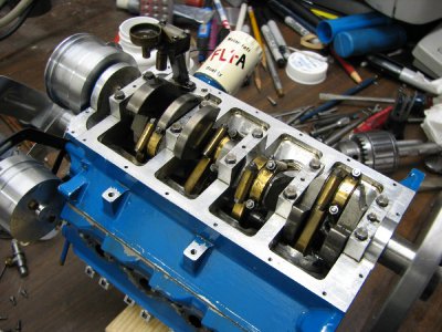
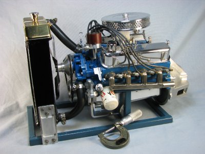
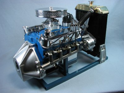
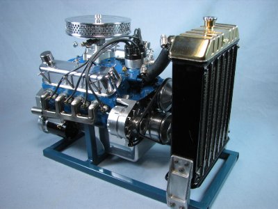
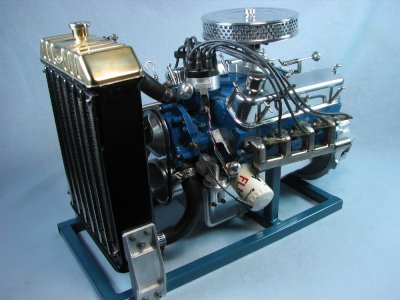
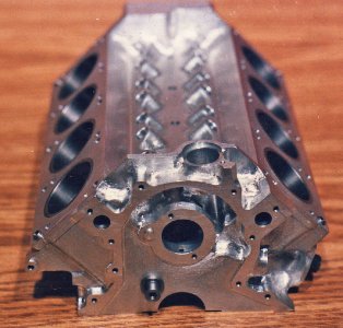
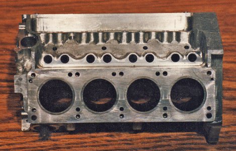
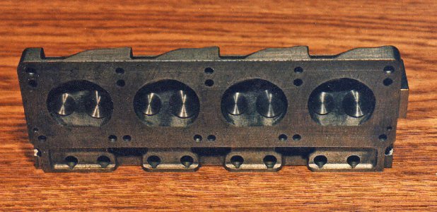
It has a bore and stroke of 1.00x.900. The block and some of the peripherals are machined from 6061 aluminum. The block was machined to form the water jackets and a head plate was bolted on to form the closed cavity. The block was then bored to accept cast iron liners. The engine has a full pressure oil system provided by a geared pump driven from the distributor shaft. The cooling system is through the block, heads and intake manifold which then returns to the radiator. Although many types of carburetion were tried over the years the one that seems to work the best is an air-bleed type modeled from an RC engine. The ignition is a Hall triggered electronic unit and will allow the engine to rev to an honest 7,800 rpm.
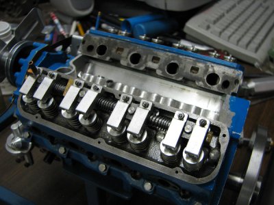
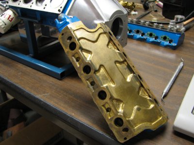
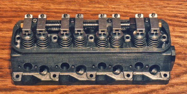
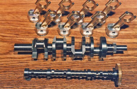
The crank and heads are iron, the cam is steel, the rods are bronze. The intake manifold was made in 2 pieces from brass so that the runners and cooling passages could be machined and then silver soldered together. The valves are stainless steel and are operated by roller rocker arms.
gbritnell


