
I am learning Fusion 360 to make 3D printed stuff. Only ever did 2D for last 25 years. I decided to do the hold-down clamps in Janderso's post. Straight lines, angles and holes. After 3 days and multiple failed attempts, I have a very nice 3D model. Now I find out that I can't get dimensions on the model. I did the sketch thing and all the dimensions showed, but wouldn't save to print. How do I draw a simple item like this with the information to build it? I use Draftsight for all my 2D drawings. Do I need to draw all this up twice? Once as 2D and again as 3D? I understand that say in a gear train you couldn't get dimensions, but on a simple block I would like to add the information. Is there a solution to my problem?

-
Welcome back Guest! Did you know you can mentor other members here at H-M? If not, please check out our Relaunch of Hobby Machinist Mentoring Program!
You are using an out of date browser. It may not display this or other websites correctly.
You should upgrade or use an alternative browser.
You should upgrade or use an alternative browser.
Fusion 360 Help
- Thread starter Chewy
- Start date
- Joined
- Feb 28, 2019
- Messages
- 499
It's not entirely clear what you are asking for - A "formal" print for a design? working drawings?
I use Fusion a lot and I'm pretty happy with it.
When working in the "design" mode, dimensions are not shown on the screen. I think it would add a huge amount of clutter. You can use inspect->measure to get dimensions directly off of the design view. If you measure point type things (actual points, corners etc) you can turn on "show xyz" to get distances in each direction, otherwise it tends to show minimum distance. This can be a little annoying when measuring between two holes for instance. All of this is interactive and probably not what you are looking for. But I have just had my laptop in the shop and used this to check stuff while I'm making it.
There is also a "drawing" mode that I've only used once or twice. With some effort (leaning how to use it) you can produce full blown shop drawings to standards. For me, this is way more than I generally need and not worth the time and effort to figure it out and use it. If I was an employee working on a project for a "real" company, then most likely that's what would be used for drawing documentation.
The other place that dimensions show up is on sketches. You can turn them on or off and you can add dimensions for pretty much anything you want. What I do is pull up the sketch, make sure it's got the dimensions I need and then do a scree shot and print it - If I really want a piece of paper to work from later on.
If you created your model using primitives in design mode (create box, cylinder, modify etc - direct modeling) then you may need to create a sketch and project the geometries you need dimensions for onto the sketch.
I generally start with a sketch and then work my model out from that, adding more sketches as needed. It did take me some time to get a general feel for this work flow. I had to develop a sense of what sketches I was going to need and try to keep them somewhat organized.
Hope that helps, If you have a more specific question there are a bunch of us here that use Fusion and there is a sub forum for it. Autodesk also has a pretty good forum, but a lot of the questions are much more "pro" orientated.
If you want a 2D drawing with dimensions, then you need to create a drawing from the model. First you create your model, say it is a square with a pocket in it. You will dimension that in the model so that your model is the correct size for what your design intent it, then you will create a traditional drawing from the model.
Most of my models are multiple components, so I create components for each part, but if you are doing a simple part like above, you don’t need to do that. In either case you will right click on the component or top level of your model and will see an option to create a drawing. Here you will select your sheet size, units of measure, etc. it will open a new sheet and bring in a view of the modeled part, you then add dimensions with tolerances if desired, multiple views, etc just like when you drew in Draftsight.
Fusion 360 is a modeling program first, so you always will have a two step process for making a print, but it is very powerful when making an assembly, you can see how the parts fit together, see if there are gaps or interferences that you did not intend, etc. There is a sectional view option in the model view so you can see internal details as well. I use it a lot for the things I build. A couple guys on YouTube were a big help in understanding the program, search for Arnold Rowntree and Lars Christensen, they have very good beginner videos and were a life saver when I first tried using the program.


- Joined
- Feb 28, 2019
- Messages
- 499
Learn something new everyday! I knew you could turn dimensions on and off within the sketch, didn't know you can pick a sketch in design and turn them on.
They are independent, you can have them on/off per sketch in either design or sketch mode and they stick depending on mode.
So that would be an option, turn dimensions on for the sketches you want and take a screen shot in the design view.
They are independent, you can have them on/off per sketch in either design or sketch mode and they stick depending on mode.
So that would be an option, turn dimensions on for the sketches you want and take a screen shot in the design view.
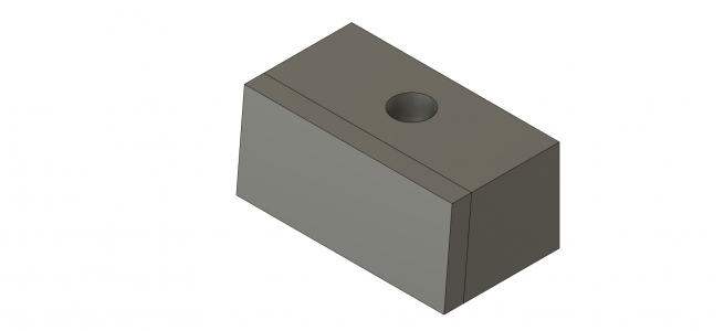
Is this the kind of view you are looking for?
View attachment 421478
Yes. Did all sorts of show dimensions and sketch dimensions but none stuck. Below is a picture of the block before dove tails. But from looking at picture what is center of hole? How wide? I will study your solution and see if I can get it to work. I started by making a box and then splitting it, was that wrong? I got some good from You Tube but more confused was like it.
Attachments

It keep saying driven dimensions and the picture that you show is what I saw. But I couldn't save it. I wanted to do top and one side for the angle. How do I keep that picture? can you do a sketch after the fact? Go around the outline of the block?
It sounds like what you want is a drawing. Really much better than trying to shoehorn a sketch into something to make a part from. The drawing function is pretty straightforward. It is limited to single sheets and counts against the ten-active-part limit though, which can be annoying.
- Joined
- Jan 21, 2013
- Messages
- 860
when you create a drawing of your part, you can select a view of the part and show the dimensions that you created earlier. You can then show different views with their dimensions, on the same page, just like the old style drafting did.
this is just the first example I found, but it's older, so things won't match up exactly. Still should get the idea across.
this is just the first example I found, but it's older, so things won't match up exactly. Still should get the idea across.