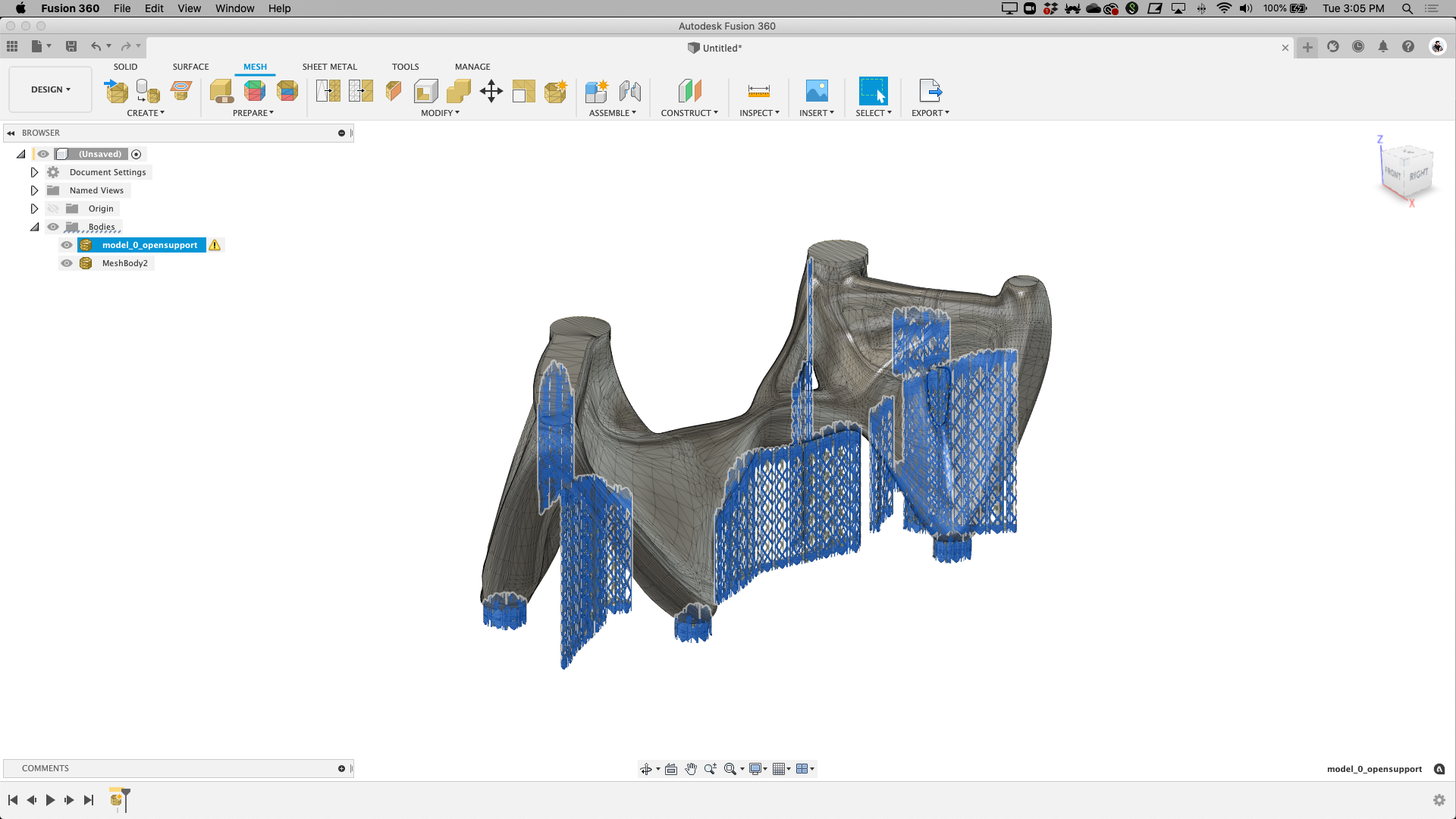
Here I was hoping you would have some kind of magic answer!  Unfortunately I had come to that conclusion also. Mr. Pete did a video on one of these using a flycutter to cut the radius out. I saw this one and thought that it was already done and I could get one printed out and ready to use. No luck. I can get dimensions off of the dial indicator and the 3D print by using the measuring tool and then modify them for an AXA holder. It will be good practice learning the Fusion. I would like to cast some steam engine bases in aluminum instead of using bar stock. I have a pile of cast iron rotors and aluminum housings to try to melt down. I have cast silver jewelry in the past using lost wax procedure and vacuum casting.
I am disappointed in the 3D thing. I have 30 year old AutoLite CAD, internet CAD drawings and misc. CAD drawings. When I open or modify them, they all stay the same. I expected the same with the .stl file and learned it isn't so. Live and learn.
Thank
Unfortunately I had come to that conclusion also. Mr. Pete did a video on one of these using a flycutter to cut the radius out. I saw this one and thought that it was already done and I could get one printed out and ready to use. No luck. I can get dimensions off of the dial indicator and the 3D print by using the measuring tool and then modify them for an AXA holder. It will be good practice learning the Fusion. I would like to cast some steam engine bases in aluminum instead of using bar stock. I have a pile of cast iron rotors and aluminum housings to try to melt down. I have cast silver jewelry in the past using lost wax procedure and vacuum casting. I am disappointed in the 3D thing. I have 30 year old AutoLite CAD, internet CAD drawings and misc. CAD drawings. When I open or modify them, they all stay the same. I expected the same with the .stl file and learned it isn't so. Live and learn.
Thank