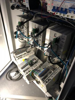
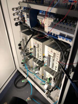
G0704 CNC AC Servo Rebuild (Picture Heavy)

Short moves showing accelerations. The servo is torque limited to 70% of continuous torque, but can go as high as 280% for brief periods of accelerations. These accelerations are pulling 40-50% of continuous torque, so I have a lot of headroom to get the accelerations increased if desired.

View attachment IMG_4183.MOV
 
That has to be the only G0704 conversion with four (!) Allen Bradley servos. I'm thinking you've got about 3 cnc'd mills worth of servos & drives (at retail price).;)

If someone makes a comment about lipstick and pigs, just grin. Well done sir.
 
If someone makes a comment about lipstick and pigs, just grin. Well done sir.

It is a pretty shade of lipstick if I do say so myself :)

I totally know this is overkill, but I had the controls, and this is the machine I had to put them on. I'm having fun!
 
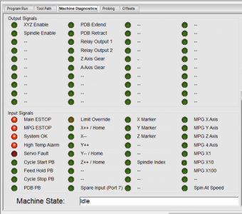
Started tonight off by modifying the default Mach 4 diagnostics window to match the inputs and outputs on my machine. All the signals for a 3 axis configuration are shown. The 4th and 5th axes would be visible in a different mach profile.

289081

Anything in RED is able to emergency stop the machine. This would be either the main or MPG estops, a failure or overload of either DC supply, the main contactor becoming de-energized (thereby powering down the drives), a high cabinet temperature alarm, or a fault on any active servo drive (which would end up messing up the part).

This works great and I was able to verify all inputs.

I started playing around with the soft limits and jogging and got repeated E21 (Aux Encoder Fault) on my X axis servo drive. This fault indicates a faulty signal transition on the Step/Dir input to the drive. Since this motor was not running, I immediately knew it was noise.

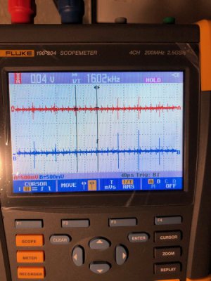
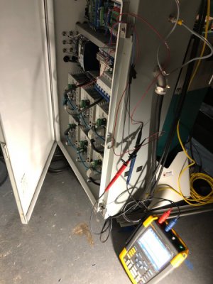
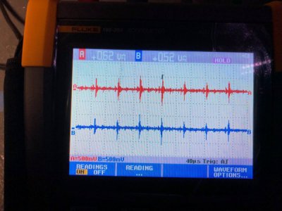
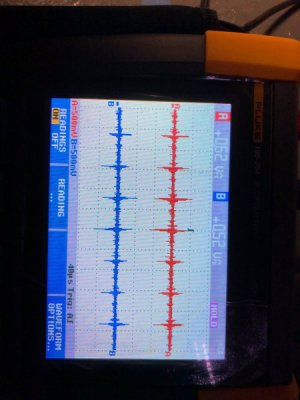
I set up my Fluke Scopemeter to measure the step and direction lines. I use the meter for work occasionally. Once the system is powered up and the axes enabled, I get an induced 16kHz pattern on both Step and Direction wires. 16kHz is the PWM carrier frequency for the servo drives.

289082

The peak to peak voltage varied, but reached as high as 1.8V. This was symmetrical about the 0V rail, so I was getting around 0.9V at the input. This cuts into the OFF noise margin which is around 1.3V. I'm sure individual spikes rose above 1.3V. This is not high enough to trigger a step, but is high enough (and more importantly brief enough) for the drive to recognize and to generate a fault.

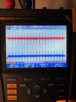
Here is a better view of the noise pattern. This is very typical of drives.

289083

I started to troubleshoot and found that the noise diminished nearly to zero once the spindle drive was shut down. Doing some E-Field sniffing with the scope probe suggested localized EMI near the Spindle drive and the Y axis Drive motor output. I was not very knowledgeable about designing for the control of EMI when I started this panel a year and a half ago, so I will take some measures to ensure solid grounding and bonding of the drives. If that doesn't work, I have LOTS of tricks up my sleeve to get this issue resolved.

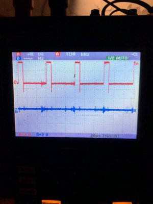
For fun, here is a view of the real step and direction signals going to the X axis motor. Note that the negative voltage spike on the falling edge of the step is most likely an artifact caused by the long test wires going to my scope.

289084

Not a ton of room to work back there...

289085
 
No pictures today. Sorry :(

I spent an hour rerouting the grounds and installing a few extra ground wires. The measured signal that was induced on the 5V wire dropped by 40-50% so the average peak is somewhere around 0.4-0.7V 0-pk. This is plenty safe for the noise margins on the input of the drive and after 2 hours of idling while enabled, no faults occurred and no stray steps were received by any drive. I still want to get this thing a little better, but it is good enough right now.

I'll be spending the weekend wedding planning, but I am hoping to have time to mount the two remaining limit switches and get the X axis installed.
 
I wonder if anyone has posted a "total" for a conversion for a G0704 machine from scratch (or others)? I subscribe to Home Shop Machinist and was sent a complementary copy of Digital Machinist. I haven't priced it on his web site, but there's an ad in there for www.cnc-minimill.com that sounds decent. It's a conversion kit for the G8689, HF 44991, Little Machine Shop #3960, MicroLux# 84630 and others.

I'm still deciding on my upgrade for a Series 1 BP with a 1983 Anilam 2-axis. Leaning now toward a Centroid Acorn controller ($300) which will also need a Windows 10 touchscreen computer (~$400). I'm going with either ClearPath or DMM 750W servos. DMM has a running ad on eBay for 3 750W plus power supply and drivers for $1150. I already have the ball screws on the table, but need to either drive the knee or convert the quill. I figure I'll have at least $3000 into the conversion.

Bruce
I have posted running totals a few times for my PM-25. Very similar machine to the G0704, just a few subtle differences. The basic stepper set up was $2271 with the mill, ballscrews, vice, electronics, etc included. A slightly better upgrade with ClearPath servos, a spindle servo (at a criminal price), enclosure, power draw bar, ATC, and tool holders comes in around $3953.
 
Certainly not a cheap hobby :D

Didn't get a ton of time this weekend to make progress on stuff, but I did finish the grounding and bonding work I was hoping to do.

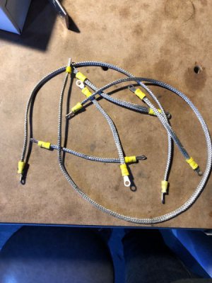
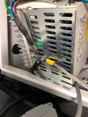
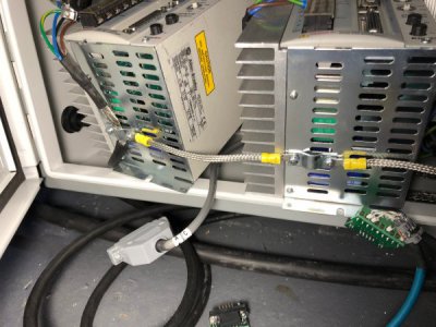
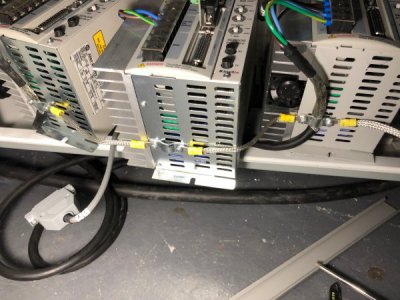
In addition to making sure the grounding was as solid as it could be, I wanted to better the bond from the case of each drive to ground (in case the aluminum subpanel and rivet nuts were not conducting through the oxide layer as well as I would like). I made up a set of braided copper bonding straps (bonding requires high surface area) to jump from drive to drive and finally back to the main grounding blocks.

289451

The bonding straps attach to the motor power clamp which is were the HF noise from the motor cable comes back.

289452

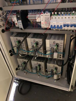
And daisy chains across the lower 3 drives. This whole process took 4 hours to disconnect the cables, unmount the drives, attach the straps, and hook everything back up. The lower 3 weren't so bad since I could rest them on the lip of the enclosure, but the upper 3 had to be hung from wires on the ceiling while I worked on them. I wish I would have done this when the enclosure was flat on the floor not mounted to the machine. But whatever, back is just a bit sore.

289454

289456

The middle drive is currently a spare, so there is no motor power or feedback cable attached.

289457

289458

All buttoned back up.

289459

After all this work, the noise level was barely reduced. This doesn't mean that the work on bonding the drive was useless (and it will probably help with the noise generated by higher currents during accel and decel), but rather that the drive to subpanel bond was sufficient and the noise is being radiated from inside the drive or somewhere else.

The signal levels remain in the 0.5-0.6V 0-pk which leaves a healthy noise margin below the 1.3V limit. I think I'm going to call it good enough at the moment, but if issues remain, I can do the following:
  • Install ferrite beads on the signal wires (max step frequency is 340kHz so 1MHz beads would be pretty good)
  • Install copper shield braid over the shielded signal cables. This could be bonded to the subpanel
  • Install separator plates inside the wire ducts
  • Cut all the servo cables to length. The spindle cables are 90' long, but I have avoided cutting them due to the fact that I paid a lot for them

289461

IMG_4271.jpg
 
With all the drives running happily, I switched back to the machine build and Mach 4.

I wanted to break the ice with LUA scripting in MAch 4 so I found a nice example of how to accomplish a timer and used it to get my power drawbar working.

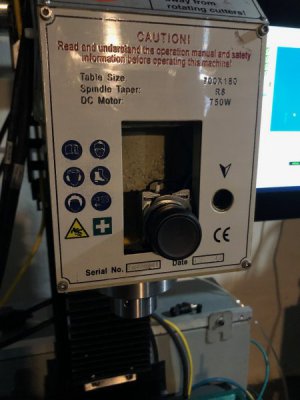
There will be a nice faceplate on the machine when I get it running (first project!), but for now the drawbar pushbutton hangs out of the front. It is an Allen Bradley 800FP series flush operator with N.O. contacts
289727

The PDB is mounted and air tight, but the drawbar needs a simple operation of the lathe and the beville spring washers installed. I want to make sure the cylinder works 100% before I do this last step.
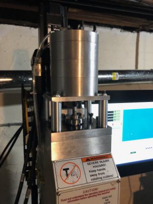
289732

Side view showing the routed pneumatic hoses and AC servo connectors. The servo cables need to be routed still.
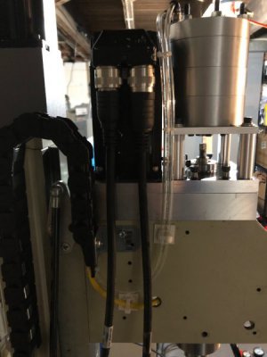
289733

Here is the solenoid hooked up. Again it is a 5 port, 4 way, 3 position, center exhausting valve. What this means is that the air cylinder can be driven both in and out, but when neither valve is energized the cylinder vents to the atmosphere and remains depressurized.
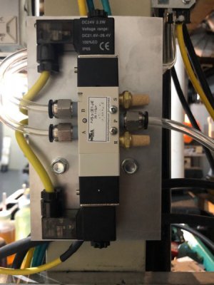
289734

Cables will tuck behind the mounting plate. A little organization is needed.
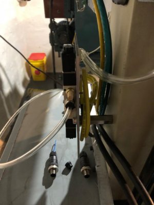
289736

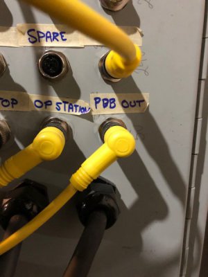
M12 cable attached to the output port. Second order of business once this machine is up and running will be to route out some label tags.
289737

Now for the code:

In the Mach 4 screen load LUA script, I added the following code:

--------------------------------------
-- PDB Timer Code --
--------------------------------------

PDBTimerPanel = wx.wxPanel (wx.Null, wx.ID_ANY, wx.DefaultPosition, wx.DefaultSize )
--This line creates a Window which has properties exposed to Win10. This window will not appear on screen, but the Windows event will be tied to it.

PDBTimer = wx.wxTimer(PDBTimerPanel)
--This line creates the actual timer 'PDBTimer' which will be referenced throughout the code
PDBTimerPanel:Connect(wx.wxEVT_TIMER,
function(event)
local PDBRetract, rc = mc.mcSignalGetHandle(inst, mc.OSIG_OUTPUT2) -- Is mapped to ESS PDB Retract

mc.mcSignalSetState(PDBRetract, 0)
mc.mcCntlSetLastError(inst, "PDB Retracted")
PDBTimer:Stop()

end)


This creates a hidden "Window" which is a Windows object. Once this is made, you can take advantage of the Windows event timer to create a delay which does not use any processor time to track. Once the timer expires, the code inside the function(event) will be run. This code writes to the PDB retract output to shut it off, displays a message at the bottom of the control, and kills the timer so it doesn't continue to loop.

In the Signals LUA script, I added the following code:

---------------------------------------------------------------
-- Power Drawbar Pushbutton
---------------------------------------------------------------
if (sig == mc.ISIG_INPUT3) and (state == 1) then
local PDBExtend, rc = mc.mcSignalGetHandle(inst, mc.OSIG_OUTPUT0)
mc.mcSignalSetState(PDBExtend, 1)
mc.mcCntlSetLastError(inst, "PDB Retracted")
end

if (sig == mc.ISIG_INPUT3) and (state == 0) then
local PDBExtend, rc = mc.mcSignalGetHandle(inst, mc.OSIG_OUTPUT0)
local PDBRetract, rc = mc.mcSignalGetHandle(inst, mc.OSIG_OUTPUT2)
mc.mcSignalSetState(PDBExtend, 0)
mc.mcSignalSetState(PDBRetract, 1)
PDBTimer:Start(500)
mc.mcCntlSetLastError(inst, "PDB Timer Started")
end


Whenever any change in signal state is detected by Mach 4, the signal script runs. By checking which signal was changed, you can execute particular chunks of code. In this case, if the changed signal was the PDB pushbutton AND the pushbutton is active, set the output PDB Extend HIGH. This energizes the "A" side of the solenoid and extends the cylinder. If the changed signal was the PDB pushbutton AND the pushbutton is not active, then the extend output is turned off, the retract output is turned on, and the timer created above is started (with an expiration time of 500ms). This causes the cylinder to retract, and that output will shut off and depressurize the cylinder 500ms later.

It is a little more complicated that the PLC stuff I normally use, but not too bad.

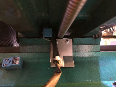
Finally I made a simple sheet metal bracket that will trigger the Y++ limit switch.
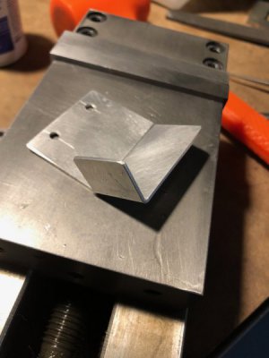
289740

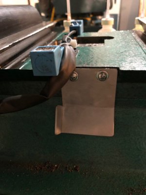
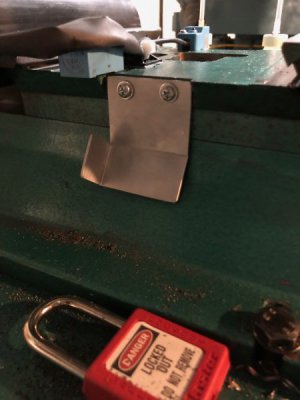
Poor lighting, but the switch will mount on the base casting and trigger when the folded flag gets close by.
289741

289742


Sorry about all the dark photos, I had already turned most of the lights off and forgot to take pictures.
 
So I've been pretty busy over the past week with this machine but didn't get quite as many pictures as I would have liked.

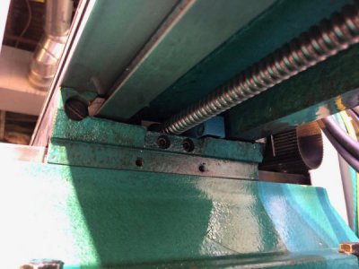
I finished mounting the Y axis limit sensors. Giving room for soft limits and the homing marker back off, I end up with around 5.90 inches of travel (This can be frustratingly small) with an absolute maximum of 6.1 inches. I could probably get another 3/8" past that if I remove the Y axis chip cover, but I really don't care to do that. Gotta live with the machine you have or buy a bigger one...

The aluminum flag doubles as a limit switch contact and a mount for the X axis limit cables (which are wrapped in unshrunk heat shrink for protection).

290270

The X axis table was mounted and the limit switches tuck neatly under the table. The end caps of the table trigger the sensors.

290271

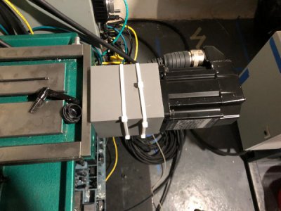
The X axis servo is mounted. Working from a CAD model bit me again and the clearance hole in the aluminum mount wasn't large enough to pass the end plate bearing block. That is probably my biggest lesson learned on this project. I set it up on my lathe and bored a couple thou off of the diameter to make the fit better. Fortunately the bolt holes were dead on.

The zip ties are temporary until I can figure out the best way to route the servo cables.

290272

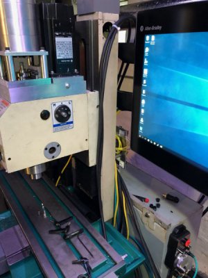
I currently have the X axis cables running down the side of the column with the connectors to the rear of the machine. This actually works decently well, but does tend to stretch the cables in front of the PC when the table is at the X-- limit and bends the cables too tightly against the base at the X++ limit. I would be VERY interested to hear any thoughts on better cable routing. Having the motor rotated so the connectors are towards the floor is worse as the cables hit the chip tray and severely limit travel.

290273

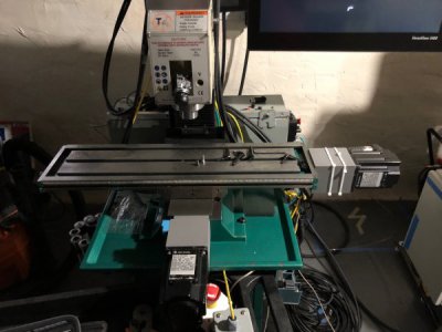
Shot of both the X and Y axes. Accounting for soft limits and marker homing, I have 17.75" of useable travel in the X axis. Not bad!

290274

No pictures yet, but I machined the drawbar collar down on the lathe to accept the stack of beville washers. This was then assembled on the machine's spindle. At first I had too many springs and the drawbar did not reach the collet with more than 1-2 threads engaged. I machined off a little more of the collar (probably at the minimum thickness now) and removed 2 springs. I have maybe 8-12 threads engaged and the drawbar actually works! I can get the tool quite tight in there (although probably not as tight as I would wrench it shut before) and the tool releases down to about 90psi. As it is assembled right now (without the 2 springs) the standoffs are about 3/8 of an inch too tall to reach the drawbar when the cylinder fires so I was testing using a piece of scrap metal in there. Once I decide on the final number of springs I will recut these to the correct length.

I noticed that adjusting the tightness of the top hat (the steel piece on top of the spindle) significantly changed how stiff the spindle is. I'm 99% sure that the length of the threaded section is too long and rather than the spindle bottoming out on the internal shoulder as it is supposed to, it is applying all the force through the pulley and into the upper two deep groove ball bearings (axial load). This is not the design intent, so I will remove the tophat and slowly work the length of the threaded section down until it bottoms out on the spindle and still maintains contact with the pulley. There is no good way for me to measure how much is needed, but it is small so I will work carefully. This way I can fully tighten the tophat without loading the spindle bearings.

I am devoting a fair bit of time to scripting in Mach 4 and will post working code as I go. My current scripts are:
  • Power drawbar control (working, but needs interlocks)
  • MPG pendant interface (in progress... Mostly done but mach is not moving with MPG yet)
  • Start, Hold, and Stop button interface (in progress, not finished)
  • Independent spindle enable (allows me to free the tool to rotate and inspect corners, not done)
  • Spindle orient (rotates the pin wrench hole to the front, unnecessary and not done)
  • Serial communications to drive (doing research, going to be hard, but will unlock a TON of features of the servos)
I also have the homing for X and Y complete. The machine homes to the switches, backs off until finding the encoder marker pulse and defines home. I need to set up indicators, but this repeats to the .0001 mark on the Mach 4 DRO.

Edit: Figured I'd also mention that I tuned the X axis servo and have it running up to 1000ipm. This is by far the smoothest of the 3 axes probably due to the double end supports on the screw. I am very happy with the performance.

Grizzly is shipping me replacement gibs for the defective ones they sent the first time. I plan to scrape (to the best of my ability) these gibs flat then cut them to length and replace the ones on the machine right now.
 
Back
Top