G0704 CNC AC Servo Rebuild (Picture Heavy)

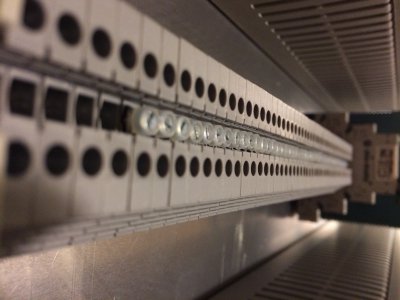
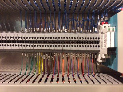
At first, I din't expect to need many terminal block connections. I installed 50 or so AB 1492-J4 terminals to be used for whatever I needed.
11.jpg

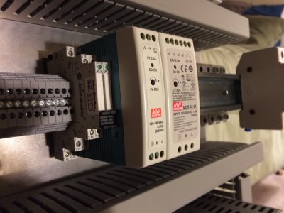
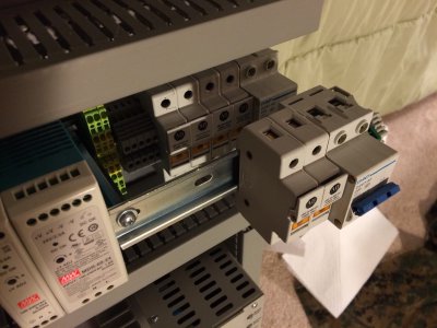
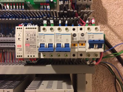
Automation Direct had a good deal on these Meanwell power supplies. They are very compact. The white cards to the left are slim AB single pole relays.
12.jpg

I quickly realized that I didn't have enough room for all seven 2-pole breakers (main + 6 drives), so I made a two tier DIN rail setup. This is the least professional part of the panel but it worked for me. I can still reach the lower breakers if I need.
13.jpg

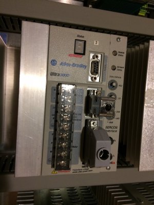
Here is a closeup of the servo drive. AB connectors for the encoder and I/O ports are crazy expensive so I bought the solder cup type off of ebay for a few dollars. I don't have any pictures of it, but I probably spent weeks soldering all the connections. It worked, but I wouldn't wish that on anyone! The encoder is a 3 row DB15 (like VGA) and the I/O is a DB44.
14.jpg

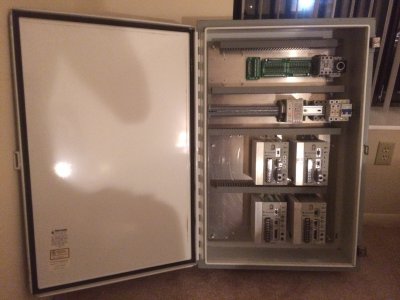
Here is the panel mounted in the enclosure.
15.jpg

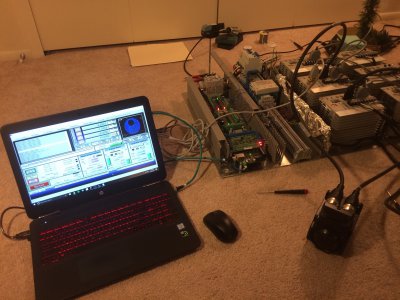
Skip ahead, and here I have some barebones wiring done. I was having some really weird faults on the drives and was testing with Mach 3. At first I thought it was noise (hence the tin foil) but later I figured out it was an obscure issue with the way I wired single ended signals into the drive I/O port.
17.jpg

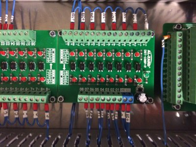
Voltage converter boards wired. I used solid core hookup wire with Panduit ferrules and wire labels froom Brady.
20.jpg

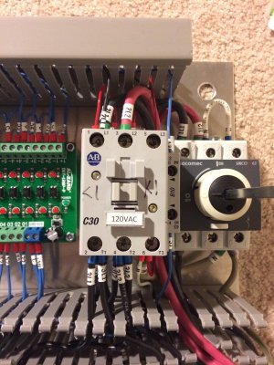
Here is another less than ideal place in my panel. The contactor served as a great place to distribute wiring from, but I ended up shoving more wires into the contacts than I should have. In hind sight, get a bigger panel and use more terminal blocks...
22.jpg

Didn't yet have all my circuit breakers in yet, but here is how it was starting to get populated.
23.jpg

and the control signal connection to the ESS on top, and the I/O cables to the drives (colored wires) on the bottom.
24.jpg

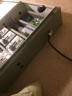
Power entered through a right angle cord gland. you can see the disconnect operator floating in the air. The little M12 connector near the top is a disconnect to shut down the contactor. This let me power cycle the drives without shutting down the whole cabinet. The black squares are 120V accessory outlets that can be switched on and off by those relays mentioned above.
26.jpg

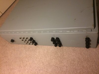
On the other side I installed (starting from the top, left side of image) a connector for the Ethernet connection to the ESS, 12 M12 ports for connecting limit switches and various I/O, and 4 rows of cable glands for the servo cables.
27.jpg
 
I don't really have any pictures of the rest of the build of the panel in my apartment, but I pretty much just ran the servo cables and stopped there. I toyed around with an automatic tool changer for the mill for a while and then shortly after I moved to a house with a basement. The rental company was kind enough to set up extra electric service in the basement for me. I still don't know why!

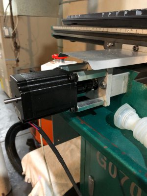
I was able to get the mill from my parents house and move it into the basement. Here is a shot of the Hoss Machine style conversion I had been using.

30.jpg

31.jpg

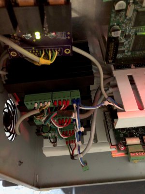
And a crappy shot inside the old control panel. I kept having these cheap stepper drives from OMC stepper online die on me. So annoying.

33.jpg

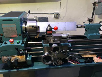
Before my mill showed up, I bought my first lathe (and joined HM!). I got to really use it for the first time to make the servo motor mounts for the conversion. This was truly the first piece of material that lathe held on to.

35.jpg

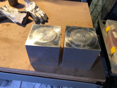
Using a parting tool and a hacksaw, I was able to cut the 4x4" aluminum bar into pieces for the mounts.

37.jpg

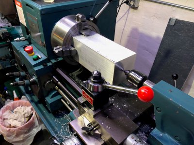
The pieces were squared in the lathe using the 4 jaw chuck. It was much faster than milling them square.

38.jpg

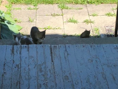
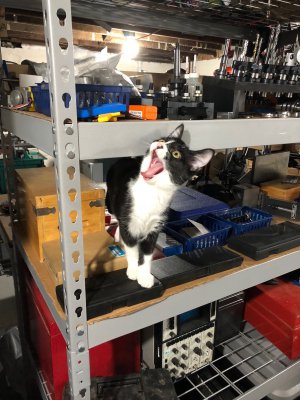
While looking back through these pictures I came across the first picture I ever took of the kittens we adopted off the street. Had to share :D They are lovely year and a half old cats now.

39.jpg
 
Partly because I was enamored with the lathe and partly because I was having issues with the CNC, I did as much work on the lathe with a boring bar as I possibly could. I really struggled with the milling on these parts due to the limited Z clearance and travel of the mill.

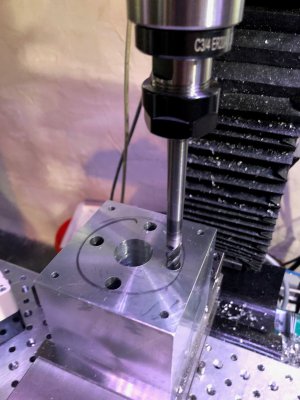
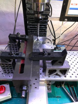
Here I was counterboring the holes for some cap screws on the Z axis using a 3/8" diameter 6" long carbide endmill.

46.jpg

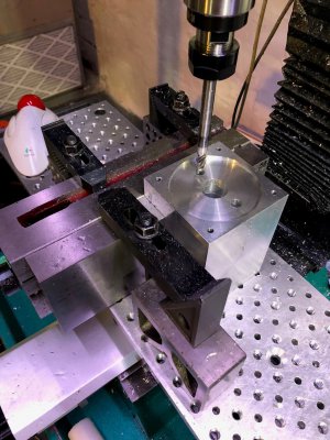
Similar machining on the Y axis mount. I had to turn the vise on its side for extra clearance.

47.jpg

48.jpg

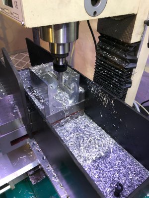
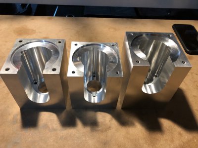
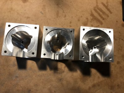
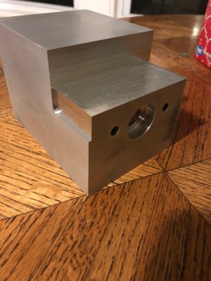
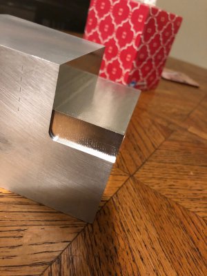
The large center bore and the bearing holes were completed on the lathe. A large bottom facing slot gives clearance to get a wrench into the mount to tighten the coupling.

50.jpg

51.jpg

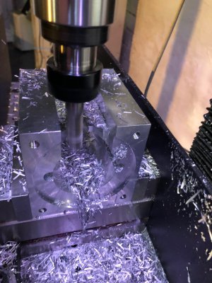
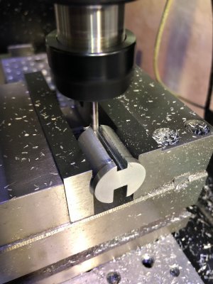
CNC made it very easy to do this slot.

52.jpg

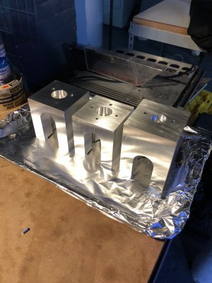
Here are the 3 finished mounted before cleanup and painting.

54.jpg

55.jpg

To paint them, I baked them in the oven to 350*F and sprayed them outside with a metal primer and Rustoleum paint. I did thin coats with a day to dry then 2-3 hour bake cycles at 200*F in between each. Maybe 10 coats in total? I found the finish to be superb and much tougher than 1 coat of paint left to air dry. It has been extremely durable.

59.jpg

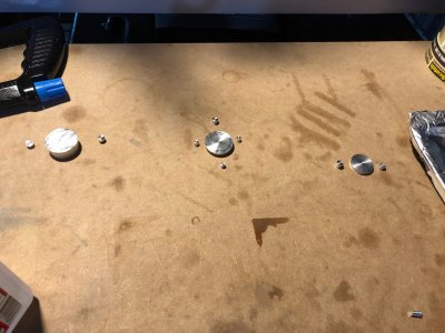
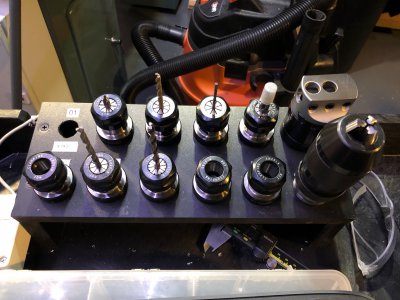
I made some shoulder pins from scrap aluminum to plug all the holes.
61.jpg

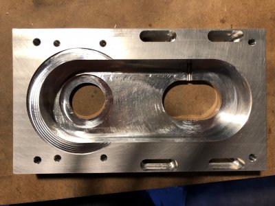
Some extra machining ended up being needed on the Y axis, so the paint was removed, machining done, then repainted.

65.jpg

66.jpg

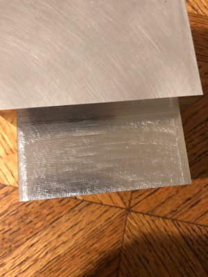
The odd floor finish comes from the machine taking many passes to remove the material. It is extremely smooth though.

67.jpg

Zoey turned into a shop kitty!

63.jpg
 
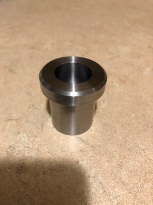
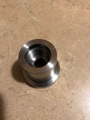
Another key part I worked on was the spindle top hat which is used by the power drawbar to release tools. This was the first internal thread I ever cut and it was against a shoulder. I made many test parts in aluminum to dial in the fit of the thread to the spindle. Unfortunately the spindle threads were completely non-standard, so it mostly took trial and error to get the right fit.

The real part was made from 41L40 steel, a first for me, which machined beautifully.

Here was a scrap test part in aluminum. My lathe always made those wavy patterns on threads, but I haven't figured out why. If you have any idea, I would love to hear it.

68.jpg

Here is the steel part, save wavy pattern. The threads work fine but it is ugly.

69.jpg

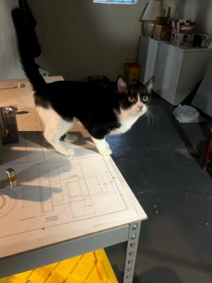
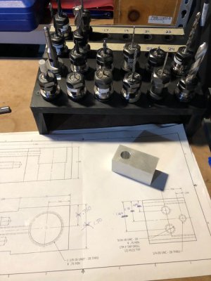
Whenever I have a bunch of parts to make, I print out my dimensioned drawing on a sheet of 11x17 and set it on my workbench with the required piece of stock. It helps me stay focused and productive. Also cat...

64.jpg

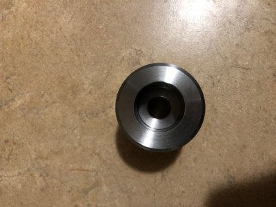
Here is the nearly finished top hat. I added two holes for a pin spanner wrench later on.

70.jpg

The drawbar is inserted through the top hat on this side with a stack of beville washers. The washers sit inside this bore.

71.jpg

Here is a shot from the back.

73.jpg
 
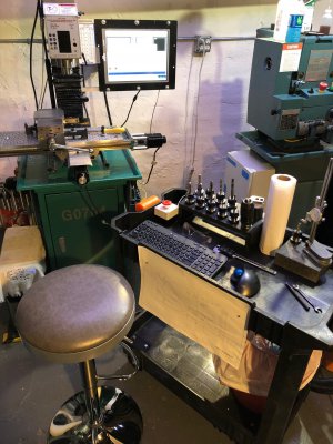
This is the way I normally work when using the CNC. This was before converting it to servos.

74.jpg

This is the motor mount plate for the spindle.

75.jpg

Next I sized and squared up the large block of aluminum that would become the spindle mount and belt guard. It was designed to be nearly air tight to minimize belt noise.

77.jpg

78.jpg

Trying to measure then length :)

79.jpg

Tools for this part loaded and ready to go.

81.jpg

Whoops! Trying to machine a very deep very narrow slot with an XL 1/8" endmill.

82.jpg

More machining on the first side using my favorite tool, a 3/8" ALU-POWER endmill from YG1.

83.jpg

85.jpg

Finished with side 1

88.jpg

Pocketing out the bottom. Off camera, I drilled a screw access hole in the side of the part for accessing the spindle motor pulley set screw.

97.jpg

Finished

99.jpg

101.jpg

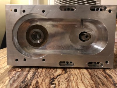
On the left is the machine spindle and tophat, on the right is a slotted system to hold the spindle motor and pulley.

103.jpg

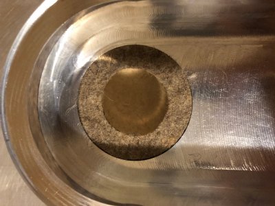
A glued in wool felt disk help keep dust out and noise in. The top hat rubs against this.

105.jpg
 
Here is a test fitting of the assembly. You can see the square nuts retained in the slots, and the top hat fed through the felt disk.

90.jpg

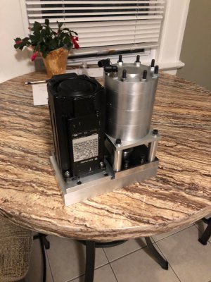
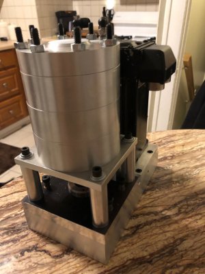
Spindle assembly with 1.8kW 5000rpm servo motor and air cylinder

108.jpg

111.jpg

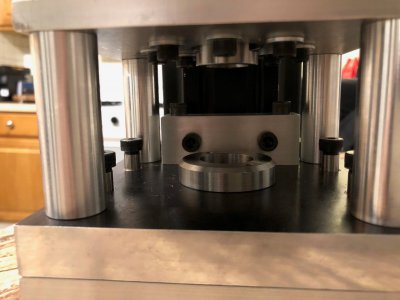
Here is the top hat assembled. When installed on the machine, it floats just clear of the black plate and holds the drawbar. The piston of the air cylinder sits overhead and squeezes the drawbar to release the tool. The black plate rides up and down on the ground shoulder bolts to grip onto the top hat.

The rectangular block behind the top hat pushes on the motor to help set the belt tension.

112.jpg

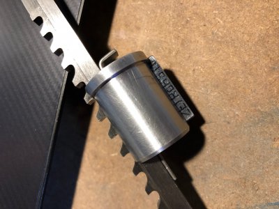
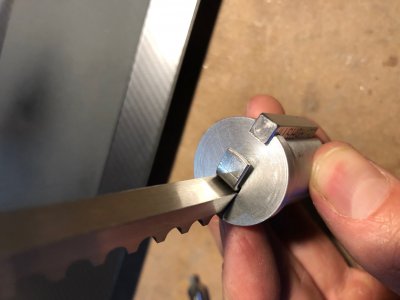
To cut the keyways in the spindle pulley, I made a custom double sided broach. This helped me cut 2 5mm keys exactly 180 degrees apart.

92.jpg

95.jpg

96.jpg
 
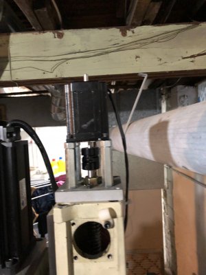
I've been noticing my Z axis has a lot of backlash right now and I suspect the bolts between the Z axis slide and the ballnut bracket have come loose. I managed to strip out one of the two threads many years ago and I'm sure the one bolt by itself wasn't up to the job.

Rather than disassembling it, finding the problem, putting it back together, making a replacement part, taking it apart, fixing it, and putting together again, I plan on just jumping straight to making the replacement. If I'm wrong, the part needed to be replaced anyways.

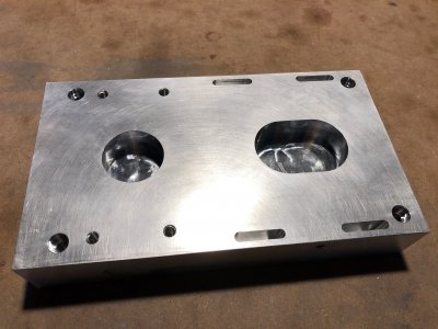
This is a part directly from the Hoss Machine conversion plans and is very simple. Most tricky part is a 1.125-18 UNEF thread for the ballnut. I can threadmill or single point this on the lathe, don't know which is easier.

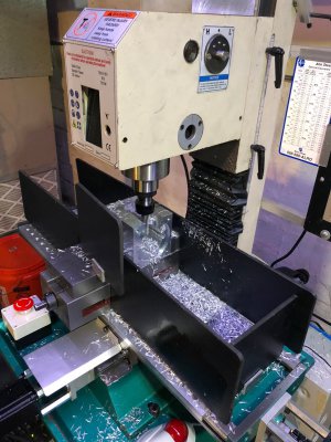
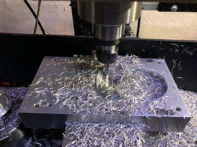
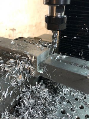
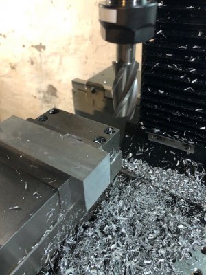
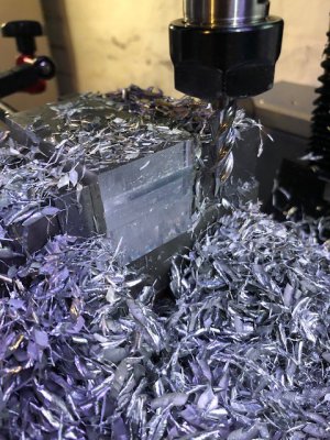
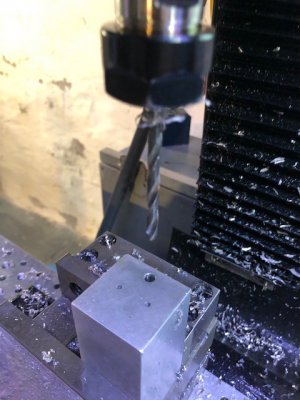
I had a piece of material with the right cross section from the get go which made this really easy. I don't have a bandsaw, so I used a 3/8" ALU-Power endmill to slot off the part. This was keyboard jogging, 2200rpm, 6 ipm, .375 depth of cut. This made great chips and sounded awesome. Used 50% of the spindle torque and around .64 HP.

1.jpg

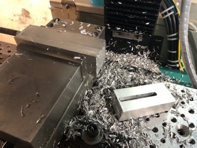
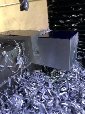
After having to flip the part to reach the final cut, the first chunk of stock was removed.

2.jpg

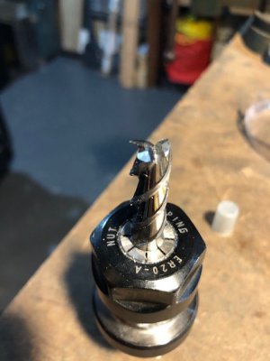
Here is that endmill. It really performs well.

3.jpg

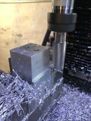
Used a 3/4" 1.5" L endmill to clean the face in one pass.

4.jpg

After marking out my final size, I sliced off another chunk in the same way as before.

6.jpg

7.jpg

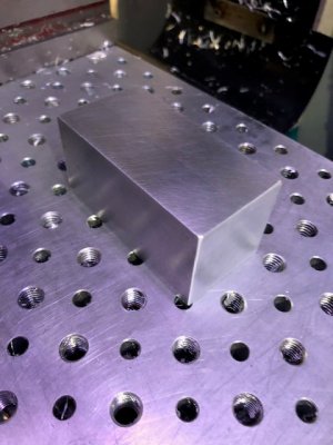
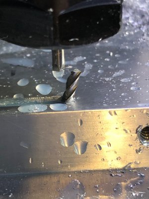
Cleaned up before working on the actual features. For punching this out extremely quickly, I was happy to hold +/- .004 on all dimensions.
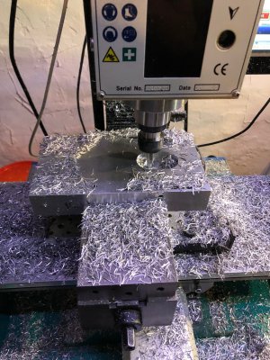
8.jpg

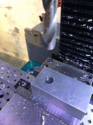
The last operation I finished yesterday was to drill the hole which will become the 1.125-18 thread. The was done in one shot with a 1/2" twist drill.
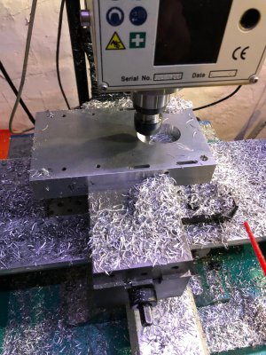
700 RPM, 3"/min, 95% spindle torque, 0.39HP (.327 calculated value, dull tool)

9.jpg

Will post more pictures as I finish this up. Supposed to be a quick N' dirty part.
 
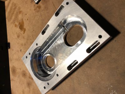
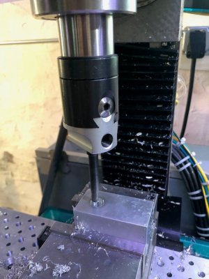
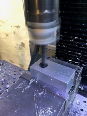
Finished some more work on this part. First was to bore the large hole out so I can get a good surface on which to indicate this part in on the lathe. I opted to thread this on the lathe so I can test fit the ballnut as I work.

1.jpg

Unfortunately I screwed up by making a change to the width of the part that wasn't shown on the print. This caused the hole to be 0.050" off center. No problem however, I just moved the boring bar to the correct location and re-bored the hole slightly larger. I still have lots of material to remove before I hit the thread minor diameter.

2.jpg

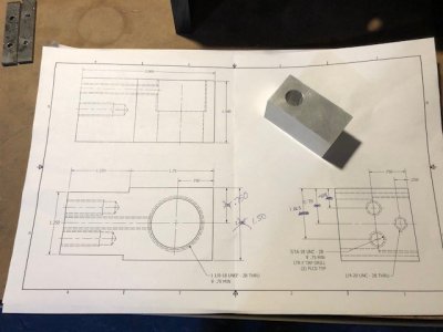
Here is the print I am working to, with some chicken scratch markups to handle the slightly wider part.

3.jpg

I have 16 tools queued up and recorded in the CNC control. Makes using MDI input easy to punch out these simple parts.

4.jpg

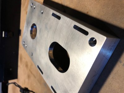
Now I flipped the part on its side to drill the two holes which mount the Z axis head to the ballnut, as well as a deep hole which allows a brass tipped setscrew to lock the ballnut into this block.

5.jpg

I added the side relief using a 3/4" 4F endmill. This must have some wear as the resulting wall varies by a few thou but is not tapered.

6.jpg

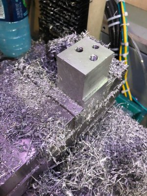
Drilled and tapped the 3 holes. The 5/16-18 holes are 1.25" deep (my 0.5" deep holes before just stripped out) and the 1/4-20 hole is 2" deep. Unfortunately my longest tap only reached 1" so I had to figure out another option.

7.jpg

I could have bought as $50 reduced shank long length nut tap, but instead I just drilled out the first 0.8" of the thread to clear the body of the tap. This let me tap the full length. Looks a bit silly though.

8.jpg

Final operation will be to bore and thread this on the lathe. Hoping to get that done tonight.

I'm also having a weird issue that just popped up where my X axis makes little ticking sounds and is slowly drifting out of position. This is very intermittent and is occasionally accompanied by the X axis drive faulting with an Aux Encoder Error (the command from Mach 4 goes into the aux encoder port). This means it is getting an illegal state transition on one of the inputs. I'm pretty sure my noise issues are back.

I don't know what changed since I was running this for weeks without issue, but as soon as I started worked on this part, I started getting noise.

I have a good plan to deal with it:
  1. Stop noise at the source by installing ferrite toroids on the servo drive outputs. I have a pair of rings for each drive which should suppress the 4kHz carrier frequency of the drive and all harmonics up to 15MHz.
  2. Install clamp on ferrite chokes to all of the signal cables coming into the drives. These are broad spectrum chokes and should allow the 5V signals to pass without impedance, but suppress spikes due to noise.
  3. Verify that the Step - and Dir - inputs on the X axis drive are not shorted to GND or DC com. This drive is weird and needs those floating for single ended inputs. When I first built this panel I was getting this same fault due to tying these pins to DC COM.
  4. Install a 1N4007 diode on each solenoid coil to suppress EMF flyback when using the Power Draw Bar
  5. Install common mode chokes on all the M12 I/O cordsets
  6. Install common mode choke on PC power cable
  7. If needed, install additional shield braid over the X axis control cable and bond it to the subpanel.
  8. If all else fails, I bought a new DB44 connector and shielded cable to replace the control wiring to the X Axis drive. I can do some better stuff with the shielding on that cable than I did in the past.
  9. If all of that fails too, I can replace the X Axis drive with a spare.
  10. Try coiling the spindle motor cables in a figure 8 pattern.
  11. If even that fails, I can cut the spindle cables to length (I left them 90' long because I couldn't bear to cut the cables I just paid a bunch of money for).
I plan on hooking up my oscilloscope to the X Axis step and direction lines so I can watch what difference each of these strategies makes on the issues. I will record what the change in measured voltage is, as well as the dominant frequency.

Finally, I have a few other things in the electrical cabinet I want to finish up:
  1. Finish marking up my AutoCAD electrical drawing package for this cabinet and verify the wiring connections match my drawing. This will be a very useful document if I need to troubleshoot something down the road.
  2. Install labels on the terminal blocks which correspond to the wire number at each point.
  3. Fix the fan connection inside the Z axis servo drive (not working currently)
 
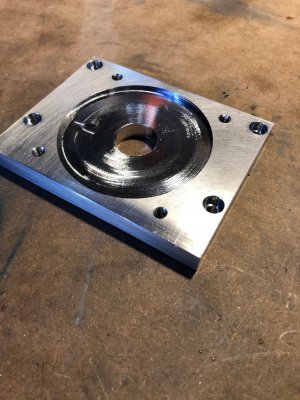
Finished up the replacement ball nut mount over the weekend. Bit more complicated than expected but very happy with the results.

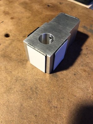
First I took the parts off the mill and added sticky backed plastic material to protect the part while clamping in the lathe.

image001.jpg

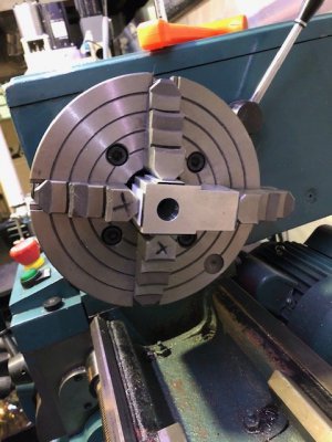
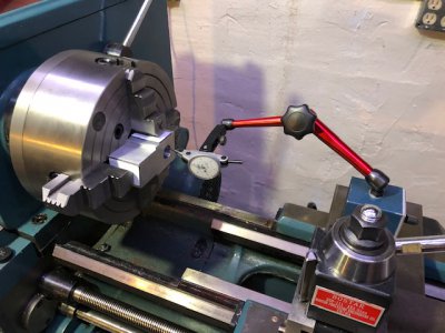
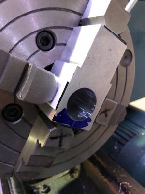
Next the part was centered on the 4 jaw chuck using a .0005" dial test indicator. I found the bore of the hole to be out of round by a little under a thou after boring on the mill. Not sure what that was about?

image002.jpg

image003.jpg

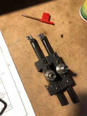
I used a small boring bar (CCGX) and a indexable threading tool (16IR) to finish the bore and create the threads.

image004.jpg

I got the thread dimensions out of the Machinery's Handbook. These were my starting point and final fitment was done with the mating part.

image005.jpg

Boring is complete. Hit the diameter right in the middle of the range for the minor diameter.

image006.jpg

Before I started threading, I wanted to get the actual ballnut out of the machine so I could get the fit of the thread exactly as I wanted it. This was no small task and I will attach a few pictures below of the process required to extract that part.

Remove air hoses...

image007.jpg

Remove servo cables, PDB pushbutton connection, remove head...

image008.jpg

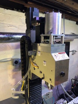
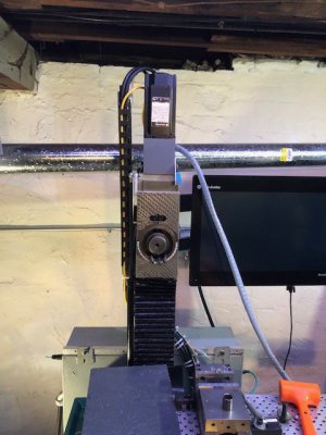
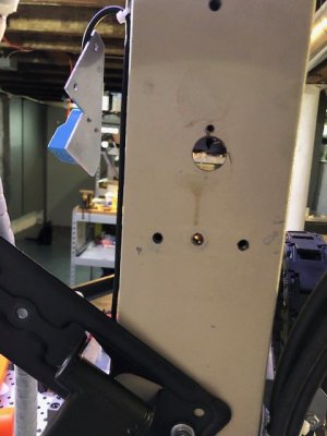
Remove Z axis slide, remove computer, remove monitor mount, remove Z axis motor, remove Z axis motor mount, remove Z axis bearing block, remove Z axis limit switch, remove Z axis gas strut, and disconnect cables from back of column. All this to get to an access hole in the back of the column to loosen a locking screw on the ballnut mount.

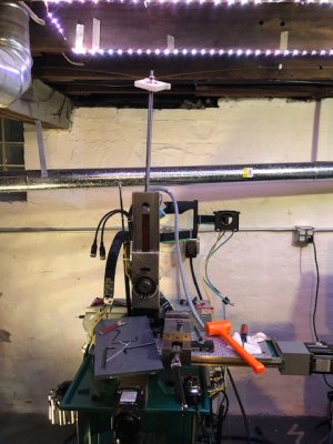
Looking quite frankenstein right now...

image009.jpg

There's the access hole.

image010.jpg

Continued on next post - too many pictures :D

-Mike
 
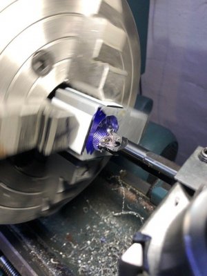
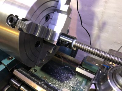
Started cutting the threads. Used steel blue and a scratch pass to make sure I got the right thread pitch.

image011.jpg

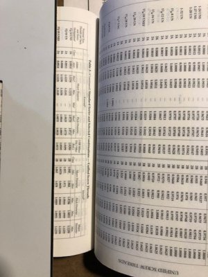
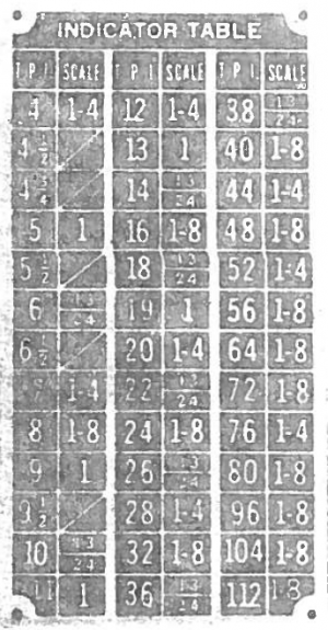
I had some issues with understanding my thread dial chart and ended up nearly destroying the threads by engaging at the wrong time. If anyone can explain to me how to interpret the 18TPI entry on this thread chart, I'd really appreciate it!

1572378950479.png

After several passes and a few spring passes, I got a really nice fit to the ballnut. I normally get a lot of chatter while threading, but it came out really nice this time.

image012.jpg

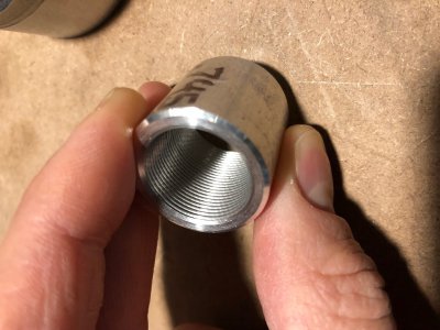
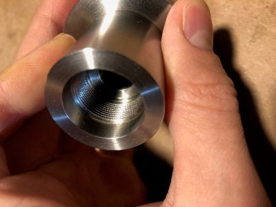
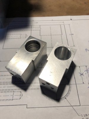
Here are the two parts, old one on the left was threadmilled on my Sherline while the right one was threaded all the way through on the lathe.

image013.jpg

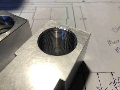
Threads look really great. Chamfer with a hand tool, not so much. Threads have a small amount of chatter but not much.

image014.jpg

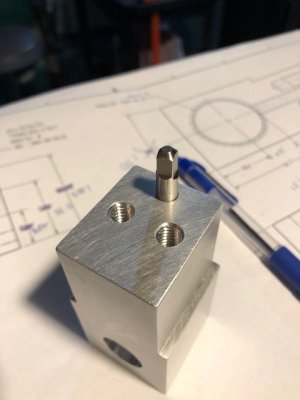
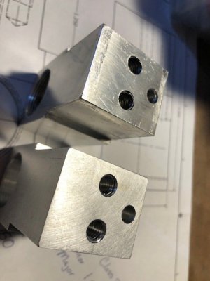
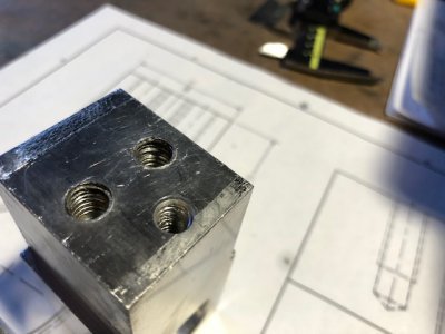
The old one on top has the two large holes stripped out. They were only drilled 1/2" deep and I guess I used the stock screws that came with the machine which only had 2-3 threads engaged into the block. The new one (bottom) has 1.5" of threads.

image015.jpg

You can clearly see the poor state of the threads here. No wonder I had .125" of backlash :oops:

image016.jpg
 
Back
Top