- Joined
- Jan 8, 2016
- Messages
- 171
Gunrunner you need to order a set of these for the Z axis hand crank. Bill did you just spit coffee on your monitor? :rofl:
View attachment 253356
View attachment 253356
The Gecko G540 has 4 inputs for limit switches, etc. Seems sort of stingy to me. I take it that for 2 switches per axis, both switches would be wired NC and in series?
What does this mean for Mach3? Does Mach3 need a separate connection for each set of limit switches for each axis?
Does Mach3 need one connection for each switch so it knows what limit it hit and therefore knows what to do?
Could all six (2-X/2-Y/2-Z) switches be wired in series on one connection?
I don’t know about the relationship between home switches and limit switches either.
You can use just one switch per axis and then install two cams
You could do this, Mach3 will stop the machine and you have to figure out which switch is tripped.
BTW, Jim, that pump you made for your coolant system is a work of art. Really impressive!
 You can build one too, as soon as you have your CNC running.
 Cams? I don't know what that is.


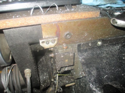
 I don't get it. That looks like a limit switch tripped by bumping into that rust colored thing. Is that rust colored thing the cam? How is that using only one switch per axis? Wouldn't you need one at each end of the axis travel? How is that one switch/axis?
You can build one too, as soon as you have your CNC running.

Apparently I am dimwitted.I don't get it. That looks like a limit switch tripped by bumping into that rust colored thing. Is that rust colored thing the cam? How is that using only one switch per axis? Wouldn't you need one at each end of the axis travel? How is that one switch/axis?
Uh, huh. I'll whip that off as my first project!
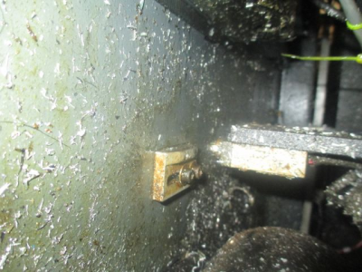
The cam is actually a ramp which depresses the roller on the switch.
One is used on each end to trip the switch
Cam, X axis. Single limit switch, two cams, one on each end of the table.
One switch. If the table moves to the left, it hits the left ramp and trips; if it moves to the right, it hits the right ramp and trips.Okeedohkee, that makes sense.
One switch/cam at each end of the axis. So, two switches per axis, right?
How can you have two cams, one at each end of the table, but only one switch?
I'm guessing that by "one switch per axis" you mean two physical switches-cams/axis, wired in series, so they act like one switch?
Am I missing something forehead slappingly obvious here?
