George Gorton Machine Company rotary table

Janderso

Jeff Anderson
H-M Platinum Supporter
Joined
Mar 26, 2018
Messages
8,407
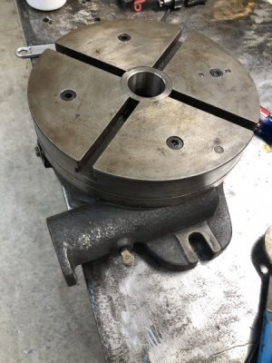
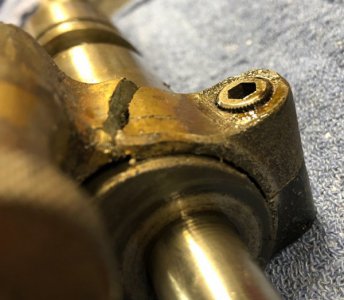
I purchased this 12” rotary table from a friend about 5 months ago.
I just now took a look at it.
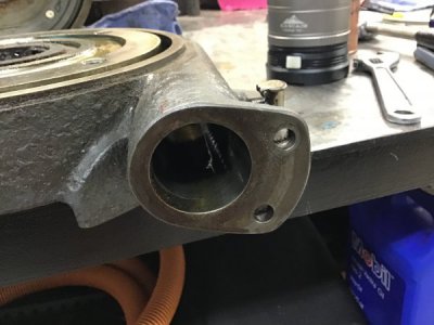
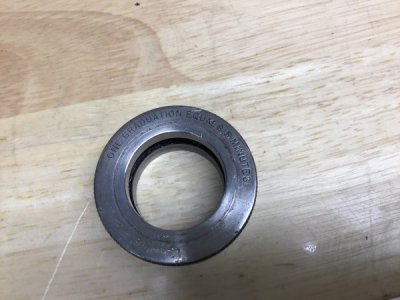
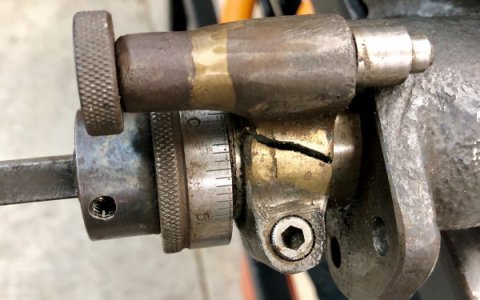
The condition is outstanding but it is broken.
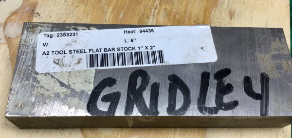
I’m hoping I can repair it.
Have you seen one of these?
The quality of the machine work is incredible.
 

Attachments

  • F2E3AAC0-4884-4E64-9918-51B7F5752BCD.jpeg
    F2E3AAC0-4884-4E64-9918-51B7F5752BCD.jpeg
    68.2 KB · Views: 48
  • 32075B7A-01AE-4288-BD36-37AA35E97E17.jpeg
    32075B7A-01AE-4288-BD36-37AA35E97E17.jpeg
    61.7 KB · Views: 47
  • 8D57019B-C5A5-4777-94FA-6C926B7D3843.jpeg
    8D57019B-C5A5-4777-94FA-6C926B7D3843.jpeg
    76.3 KB · Views: 56
  • 56B620E6-6EAC-401D-A4A4-10C271BF76EC.jpeg
    56B620E6-6EAC-401D-A4A4-10C271BF76EC.jpeg
    49.5 KB · Views: 60
  • FCB4F372-26F6-456E-B012-7377B559F9AA.jpeg
    FCB4F372-26F6-456E-B012-7377B559F9AA.jpeg
    53.9 KB · Views: 62
Hi Jeff: brazing is probably your best option, of course it will warp a little but maybe that won't matter too much? Not enough surface area for epoxy repair unfortunately
Mark
 
Plus one one on brazing it up, vee it nearly through on the break, and pre-heat till it
quits smokin then braze it up.....................My $.02.............. :grin:
 
I was taking a closer look this morning, do you notice all the brass in the area?
This has been repaired before.
Probably crashed at some point.
I may just fabricate a new piece, it's broken and cracked in three places.
Looks like a good winter project.0193A9DF-A916-4B51-A032-C694BD72AF5B.jpegF243EFC7-2E71-4D6E-BDD1-A5EE31E63086.jpeg8E12212E-97EF-4BDE-A638-A3575D401FFF.jpeg
 
Last edited:
Looks like it was already broken and repaired before it broke again. I wonder if it was dropped vs being ran into or hit with a hammer or something like that???
 
I agree, it was repaired at least once. Then either way over tightened, Not a good repair, or the bore inside was not re-machined well after the repair.

I would consider a lock washer, or locktight for the allen bolt. It fust needs to be snug enough to hole the crank spindle, the pin keeps it in location. Once it is adjusted right, the allen bolt should not need to be touched again.
 
Too bad, everything is smooth as glass. Very well made.
I love good ole USA manufacturing.
 
This is when I wish I was not such a baboon at drafting/cad/fusion 360 ya da ya da.
I need to design a locking collar that fits on the shaft that cams over the drive gear for the table rotation.
I want to be able to unlock to spin freely.
I don’t think it would be too difficult but I would need to plan exact dimensions.
If placed in this position it works, rotates very smooth.
What do you think? Can I pull it off?
Have a sliding pin on a lockable collar, made to cinch down on the shaft when set to free wheel or drive the table.
Yeah, I can do it.
Oh the pic? Yeah, 103 outside, 79 in the shop
 

Attachments

  • 111A12C1-D4B2-44A6-9E47-DFFBA6624B6F.jpeg
    111A12C1-D4B2-44A6-9E47-DFFBA6624B6F.jpeg
    25.7 KB · Views: 23
This is when I wish I was not such a baboon at drafting/cad/fusion 360 ya da ya da.
I need to design a locking collar that fits on the shaft that cams over the drive gear for the table rotation.
I want to be able to unlock to spin freely. If I see this right, you want the shaft to tiurn freely, not the collar on the shaft.
I don’t think it would be too difficult but I would need to plan exact dimensions.
If placed in this position it works, rotates very smooth.
What do you think? Can I pull it off?
Have a sliding pin on a lockable collar, made to cinch down on the shaft when set to free wheel or drive the table.
Yeah, I can do it.
Oh the pic? Yeah, 103 outside, 79 in the shop
Here is my vision. Cut from a single rectangle of steel. As I see it, the spring pin does not heed to be so long, the same thickness as the band would do. The critical dimensions I see, are the size of the large hole, and the distance to the small hole. I do not see why the collar lock bolt cannot be on the side opposite to the lock pin. I would size the large hole, so that it starts out as a tight fit on the shaft, or even so you need to pry the slot a tad, to get it to slide. That way there is not a lot of tightening needed for the collar to hold tight. I would just use a nut and bolt, unless you want to get fancy, and tap and counter bore for the original allen screw look.

Here is a quick and dirty of my thinking. Again, the locking pin would be a short one, not long like the original. This was in MS Paint, I am even more of a baboon with anything more powerful. The lower pic, shows the short pin, and the step needed for the pin hole. The to[p cap, could be threaded, welded, or pined.

quickanddirty.png
 
Last edited:
Super man,
I like your idea much better than my first sketch.
I’ll incorporate your idea with my measurements.
Thank you
Oh, I have a block of A2 tool steel
 

Attachments

  • F9A8EB27-7EF5-4984-826F-CBBFBED7DB05.jpeg
    F9A8EB27-7EF5-4984-826F-CBBFBED7DB05.jpeg
    47.9 KB · Views: 20
  • 5772E57A-D1D9-4576-8EB3-EE7CED4E3F9E.jpeg
    5772E57A-D1D9-4576-8EB3-EE7CED4E3F9E.jpeg
    41.2 KB · Views: 19
  • 8AF3498D-5DF0-4E1E-B9AA-5C79A6126078.jpeg
    8AF3498D-5DF0-4E1E-B9AA-5C79A6126078.jpeg
    47.1 KB · Views: 17
  • 0CA40ABE-011D-4303-B87A-84A3C1BA939E.jpeg
    0CA40ABE-011D-4303-B87A-84A3C1BA939E.jpeg
    43.3 KB · Views: 17
Back
Top